Highway drainage system and novel expressway

A technology for highways and drainage systems, applied to waterway systems, drainage structures, water supply devices, etc., can solve problems such as high cost of repair projects, impact on driving safety, damage to highways, etc., to prevent roadbed soil from collapsing and control quality , the effect of low flatness

Inactive Publication Date: 2019-06-21
张健俣
View PDF5 Cites 3 Cited by
  • Summary
  • Abstract
  • Description
  • Claims
  • Application Information

AI Technical Summary

Problems solved by technology

[0008] The technical problem to be solved by the present invention is to solve the problem that the drainage system of the expressway in the prior art is easy to cause damage to the expressway due to rainwater splashing when it discharges rainwater, which affects driving safety, and it is difficult to repair and repair in a short time after the expressway is damaged. Technical defect of high engineering cost

Method used


Image

  • Highway drainage system and novel expressway
  • Highway drainage system and novel expressway
  • Highway drainage system and novel expressway

Examples


Embodiment 1

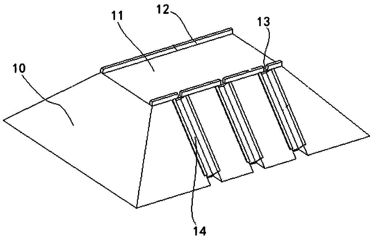
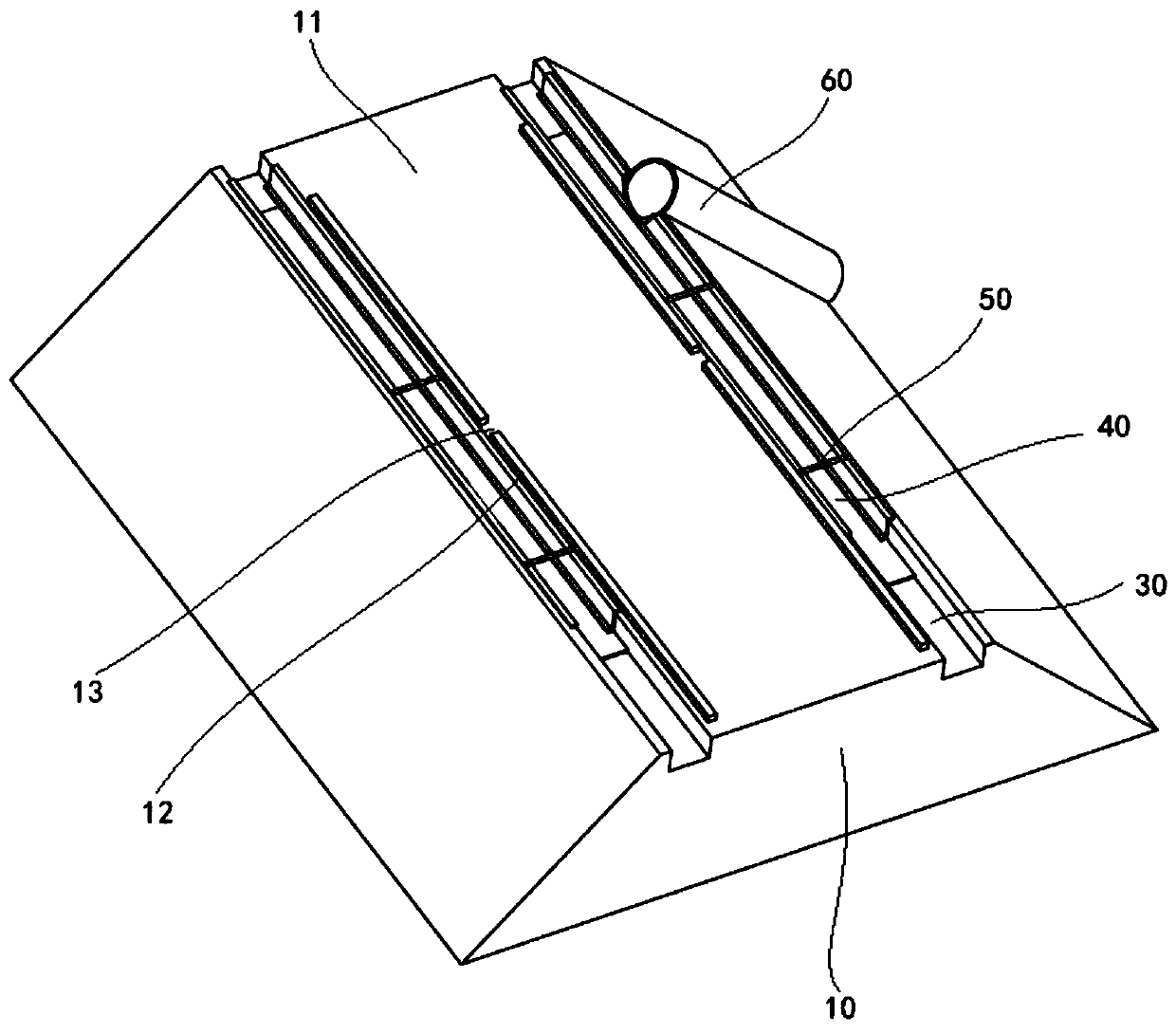
[0034] A kind of novel expressway of present embodiment, has such as image 3 The high-fill road section and cut-cut road section shown, the new expressway has a corresponding high-fill drainage system and cut-cut drainage system.

[0035] Among them, high-fill road sections such as image 3 As shown, there is a high-fill roadbed 10 and a high-fill road surface 11. The two sides of the high-fill road surface 11 are provided with water-retaining belts 12 extending along the length direction of the road near the edge. There is a drain 13 from the distance. Preferably, in this embodiment, the distance between adjacent water outlets is 20-25m.

[0036] As the biggest improvement of this embodiment, such as image 3 As shown, the new expressway subverts the design concept of the traditional high fill drainage system, and a side ditch 30 is set on the outside of the water retaining belt, and the side ditch 30 is used for centralized collection of rainwater on the high fill road. ...

Embodiment 2

[0045] The new expressway of this embodiment, on the basis of the high fill section described in Embodiment 1, in figure 2 In the excavated road section shown, a drainage groove 40 made of corrugated steel as described in the first embodiment is also arranged in the side ditch 30 . In addition, at the junction of the high fill roadbed 10 and the excavated roadbed 20, a centralized drainage pipe made of steel bellows is also provided.

[0046] In this embodiment, both the high-fill drainage system and the excavation drainage system adopt the drainage groove made of corrugated steel and the centralized drainage drainage pipe made of steel corrugated pipe, which further improves the drainage performance and Safety performance, can adapt to more terrains, and has lower requirements on foundation bearing capacity and flatness, which is beneficial to improve the uneven settlement problems in special foundation structures such as permafrost, soft soil, expansive soil, and collapsibl...

Embodiment 3

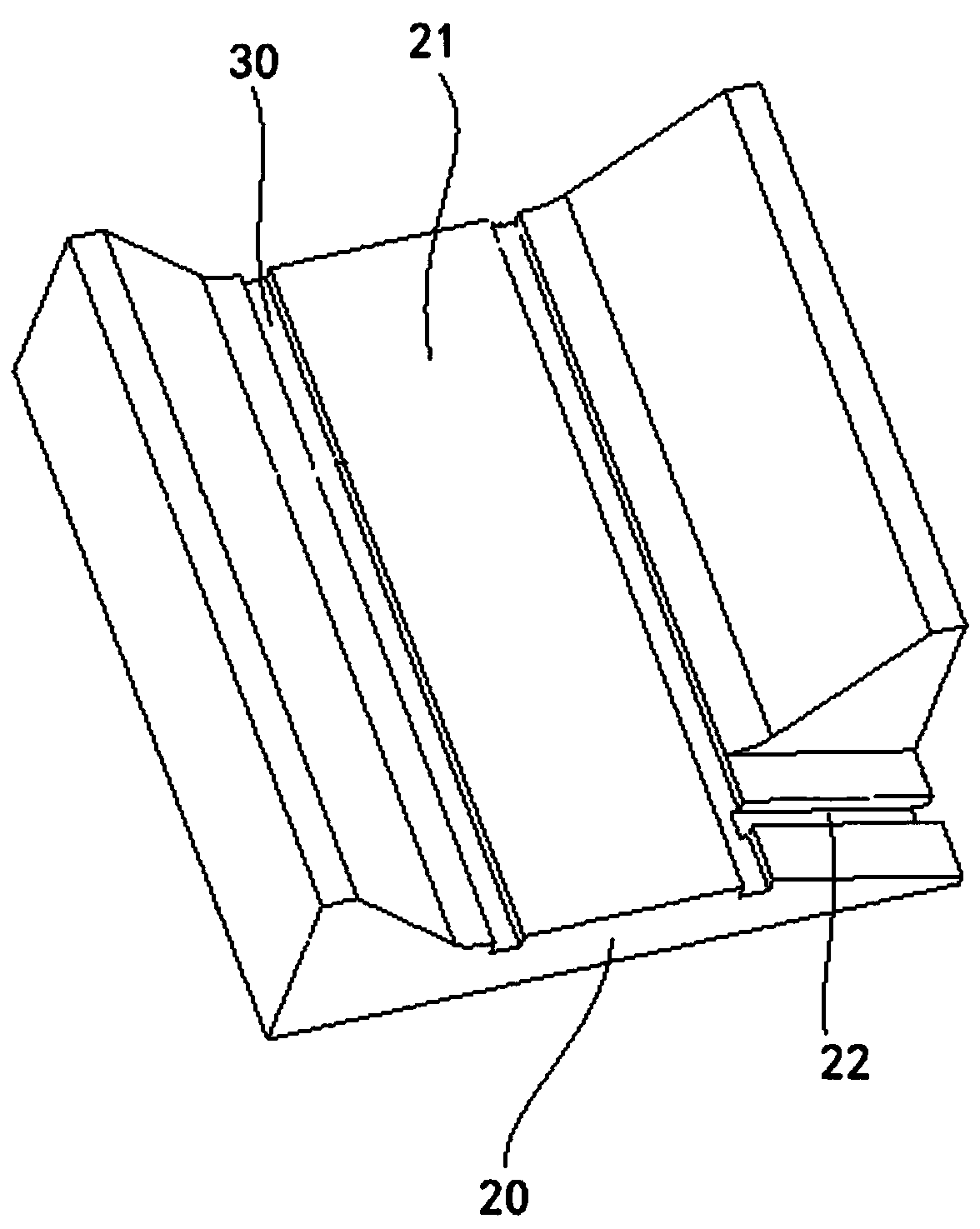
[0048] A kind of road drainage system of the present embodiment has such as Figure 4 The shown drainage groove 40 for adapting to the side ditch of the road, the drainage groove 40 is formed by connecting end to end of several drainage groove units, and the adjacent drainage groove units are connected by sealant, gasket or other conventional, Seal with a suitable sealing method to prevent water leakage at the interface. Wherein, the drainage tank unit includes a tank bottom 41 and tank walls 42 arranged on both sides of the tank bottom. It should be noted that the tank wall 42 and the tank bottom 41 can be integrally formed, or can be designed separately and fixed together by bolts, welding and other means.

[0049] As a preference, in this embodiment, as Figure 4 As shown, the tank wall 42 and the tank bottom 41 are designed separately. Wherein the groove wall 42 has a lower edge 43 for connecting with the groove bottom 41 and an upper edge 44 for overlapping the high fi...


PUM


Abstract

The invention relates to the technical field of highway drainage, and particularly discloses a highway drainage system and a novel expressway. A high-fill drainage system of the novel expressway comprises a side ditch and a drain pipe made of a steel bellows, wherein a drainage tray is installed in the side ditch, the drainage tray is formed by a plurality of drainage tray units connected end to end, each drain tray unit comprises a tray bottom and tray walls arranged on two sides of the tray bottom, and the tray bottoms and the groove walls are all made of corrugated steel. The high-fill drainage system overturns the design concept of the traditional high-fill road section drainage system; through centralized concealed drainage, rainwater can be effectively prevented from overflowing intosubgrade soil, then preventing damage to a subgrade soil body structure and even subgrade soil body collapse caused by rainwater overflow; the drainage tray and the steel bellows have the advantage that the ability of adapting to subgrade deformation is strong, and have lower requirements on the bearing capacity and flatness of a foundation, the differential settlement problem of special foundation structures such as permafrost, soft soil, expansive soil and collapsible loess can be favorably solved.

Description

technical field [0001] The invention relates to the technical field of highway drainage, in particular to a highway drainage system and a new expressway. Background technique [0002] According to JTJ / T D33--2012 "Code for Design of Highway Drainage", the surface drainage of the road surface should meet the following requirements: 1. The water on the surface of the road surface in the cutting section should be collected in the side ditch through horizontal drainage; 2. The embankment is high and the slope is high. If the surface is not protected, or if the slope has protective measures but may still be scoured, the road surface centralized drainage system should be used to drain the road surface water; 3. Concentrate vertically downward on the embankment, cutting slope or slope platform When draining water, it is advisable to set up rapid flow troughs, side ditches, intercepting ditches, and drainage ditches to drain rainwater to low-lying places, so as to avoid the scouring...

Claims


Application Information

Patent Timeline
Patent Type & Authority Applications(China)
IPC IPC(8): E01C11/22E03F5/04
Inventor 张健俣张震韬邸雪妍
Owner 张健俣
Why Eureka
Try Eureka