Three-stage power transmission system of vertical circulating stereo garage

A technology of power transmission system and three-dimensional garage is applied in the field of three-stage transmission system, which can solve the problems of contact surface damage and failure, and achieve the effect of high degree of bonding, noise reduction, and prevention of transmission failure.

Pending Publication Date: 2019-06-21
SHANDONG JIU ROAD PARKING EQUIP CO LTD
View PDF0 Cites 2 Cited by
  • Summary
  • Abstract
  • Description
  • Claims
  • Application Information

AI Technical Summary

Problems solved by technology

In the industry, due to the difficulty of manufacturing and cost considerations, the material of the shift fork wheel is generally 40Cr, and the tooth groove surface is subjected to high-frequency quenching treatment, but the application results prove that the tooth groove of the shift fork wheel is due to extrusion Insufficient strength and anti-wear performance will cause damage and failure of the contact surface to be common.

Method used


Image

  • Three-stage power transmission system of vertical circulating stereo garage
  • Three-stage power transmission system of vertical circulating stereo garage
  • Three-stage power transmission system of vertical circulating stereo garage

Examples


Embodiment 1

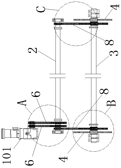
[0042] Example 1. Such as Figure 1-4 , as shown in 7-8, a three-stage power transmission system for a vertical circulation three-dimensional garage, is characterized in that: the transmission system includes a main motor 101, a reduction motor 1, a secondary transmission shaft 2, a tertiary transmission shaft 3, two The first-stage transmission shaft 2 is arranged between the geared motor 1 and the third-stage transmission shaft 3 and is parallel to the power output shaft 11 and the third-stage transmission shaft 3 of the geared motor 1; between the geared motor 1 and the second-stage transmission shaft 2, the second-stage transmission The shaft 2 and the third-stage transmission shaft 3 are all connected by chain transmission; the third-stage transmission shaft 3 is provided with a circulating chain drive wheel 4; the main motor 101 is connected with the reduction motor 1 .

[0043] The transmission system includes a reduction motor 1, two primary transmission sprockets 5, ...

Embodiment 2

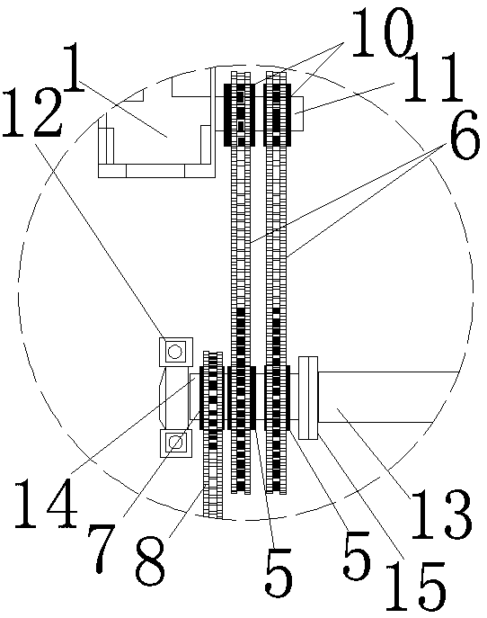
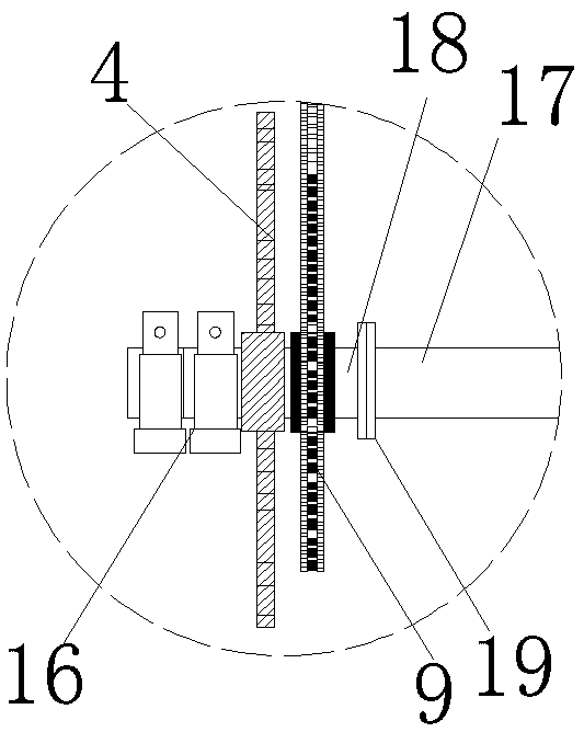
[0059] Example 2. Such as Figure 5-6 As shown, the difference between this embodiment and Embodiment 1 is that the transmission system includes a reduction motor 1, a primary transmission sprocket 5, a primary circular transmission chain 6, a secondary transmission shaft 2, and two secondary transmission chains Wheel 7, two secondary endless drive chains 8, tertiary drive shaft 3, two tertiary drive sprockets 9, two loop chain drive wheels 4.

[0060] The secondary transmission shaft 2 , the tertiary transmission shaft 3 , and the PTO shaft 11 of the geared motor 1 are parallel to each other, and the secondary transmission shaft 2 is arranged between the tertiary transmission shaft 3 and the PTO shaft 11 of the geared motor 1 .

[0061] The power output shaft 11 of the reduction motor 1 is provided with a power output wheel 10; the primary transmission sprocket 5 is arranged on the secondary transmission shaft 2 and is in the same plane as the power output wheel 10; the powe...


PUM


Abstract

The invention discloses a three-stage power transmission system of a vertical circulating stereo garage. The transmission system comprises a main motor, a gear motor, a second-stage transmission shaftand a third-stage transmission shaft, wherein the second-stage transmission shaft is arranged between the gear motor and the third-stage transmission shaft and is parallel to a power output shaft ofthe gear motor and the third-stage transmission shaft; the gear motor is in transmission connection with the second-stage transmission shaft through a chain; the second-stage transmission shaft is intransmission connection with the third-stage transmission shaft through a chain; and a circulating chain driving wheel is arranged on the third-stage transmission shaft. According to the three-stage power transmission system, the stress condition of the transmission shaft can be effectively improved, and the operation safety and stability of equipment are more reliably guaranteed.

Description

technical field [0001] The invention relates to the field of three-dimensional garages, in particular to a three-stage transmission system for a vertical circulation three-dimensional garage. Background technique [0002] The vertical circulation three-dimensional garage that provides on the market at present, the transmission mode that adopts is the chain dial type secondary transmission system. Such as Figure 9-12 As shown, each fork wheel 25 of the vertical circulation three-dimensional garage is connected with a lifting chain 21 respectively; Two lifting chains 21 are respectively installed on the left and right ends of the frame body 20; Plate 22 and the vehicle-carrying chain plate 22 of the same height are provided with vehicle-carrying hanger installation crossbar 23, and vehicle-carrying hanger installation crossbar 23 is equipped with vehicle-carrying hanger 24. The reduction motor 1 links to each other with the sprocket 26 through the transmission chain 27, and ...

Claims


Application Information

Patent Timeline
Patent Type & Authority Applications(China)
IPC IPC(8): E04H6/18E04H6/42F16H7/06
Inventor 陈金水
Owner SHANDONG JIU ROAD PARKING EQUIP CO LTD
Why Eureka
Try Eureka