
Engine rotating speed regulating device based on controller area network (CAN) and method

A technology of engine speed and adjusting device, which is applied in the field of CAN bus, can solve the problems affecting vehicle driving performance and safety, low stability, poor reliability, etc., and achieve the expansion of modification space, strong anti-interference ability, and good use effect Effect

Pending Publication Date: 2019-06-21
DONGFENG MOTOR CORP HUBEI
View PDF6 Cites 2 Cited by
  • Summary
  • Abstract
  • Description
  • Claims
  • Application Information

AI Technical Summary

Problems solved by technology

[0002] The traditional speed adjustment device adopts the method of disconnecting the original vehicle throttle signal input, and connecting the microcontroller to simulate the throttle, and inputting a voltage signal to adjust the engine speed. This control strategy has a great impact on the original vehicle throttle signal and affects the driving performance of the vehicle. And safety, low stability, poor reliability, generally used in parking situations

Method used


Image

  • Engine rotating speed regulating device based on controller area network (CAN) and method
  • Engine rotating speed regulating device based on controller area network (CAN) and method

Examples


Embodiment Construction

[0020] Below in conjunction with accompanying drawing and specific embodiment the present invention is described in further detail:

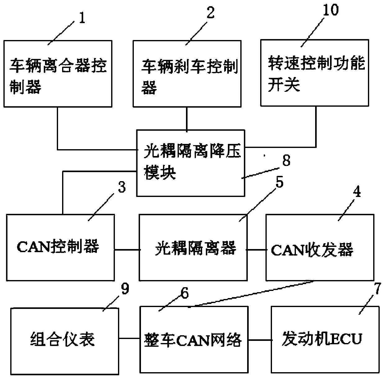
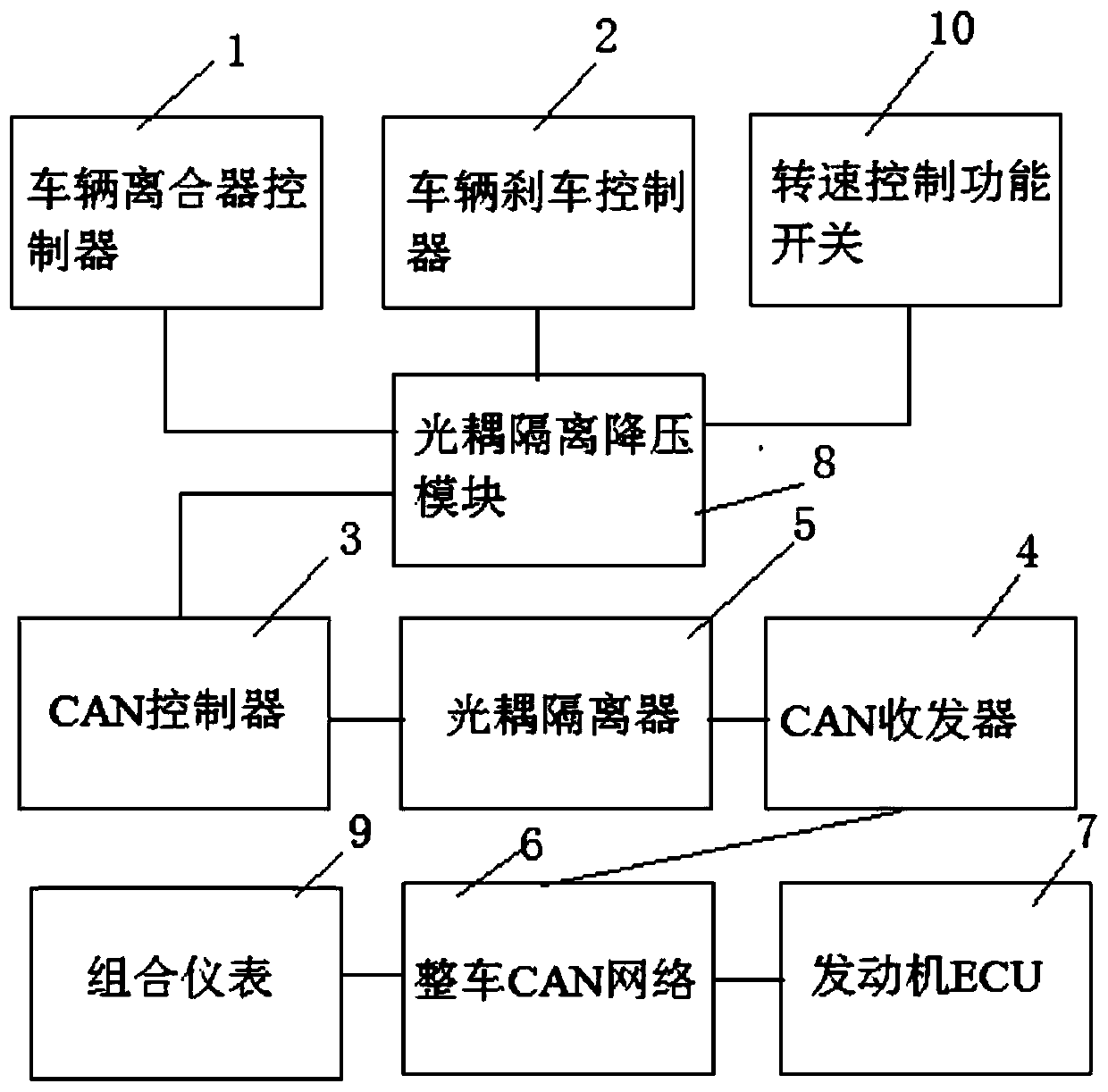
[0021] A CAN-based engine speed regulating device designed by the present invention, such as figure 1 As shown, it includes a vehicle clutch controller 1, a vehicle brake controller 2, an optocoupler isolation step-down module 8, a CAN controller 3, a CAN transceiver 4 and an optocoupler isolator 5;

[0022] The clutch state signal output end of the vehicle clutch controller 1 is connected to the clutch state input end of the CAN controller 3 through the optocoupler isolation step-down module 8, and the brake state signal output end of the vehicle brake controller 2 is through the optocoupler isolation step-down module 8. Connect the brake state signal input terminal of the CAN controller 3, the CAN controller 3 has the vehicle engine target speed value input interface (for writing the target speed), the engine speed of the CAN controller 3 requ...


PUM


Abstract

The invention discloses an engine rotating speed regulating device based on controller area network (CAN). The output end of a clutch state signal of a vehicle clutch controller of the engine rotatingspeed regulating device is connected with the clutch state input end of a CAN controller through an opto-coupler isolation step-down module, the output end of a brake state signal of a vehicle brakecontroller is connected with the input end of the brake state signal of the CAN controller through the opto-coupler isolation step-down module, the communication end of an engine rotating speed request TCS1 message format sequence transistor-transistor logic (TTL) signal of the CAN controller is connected with the communication end of the engine rotating speed request TCS1 message format sequenceTTL signal of a CAN transceiver through a photon coupled isolator, and the communication end of an engine rotating speed request TCS1 message format sequence CAN bus differential signal of the CAN transceiver is used for being connected with the communication end of a CAN bus of an engine electronic control unit (ECU) through a vehicle CAN network. According to the engine rotating speed regulatingdevice based on the CAN, the engine rotating speed outputs steadily, and guarantee is provided for the vehicle chassis electric and power taking requirements for equipment on the vehicle.

Description

technical field [0001] The present invention relates to the field of CAN (Controller Area Network, CAN, Controller Area Network) bus technology, in particular to a CAN-based engine speed regulating device and method. Background technique [0002] The traditional speed adjustment device adopts the method of disconnecting the original vehicle throttle signal input, and connecting the microcontroller to simulate the throttle, and inputting a voltage signal to adjust the engine speed. This control strategy has a great impact on the original vehicle throttle signal and affects the driving performance of the vehicle. And safety, low stability, poor reliability, generally used in parking situations. Contents of the invention [0003] The invention provides a CAN-based engine speed adjustment device and method. The invention aims to realize high-precision, stable and more reliable control of the running speed of the vehicle-mounted engine under driving and parking conditions, and ...

Claims


Application Information

Patent Timeline
Patent Type & Authority Applications(China)
IPC IPC(8): F02D11/10F02D31/00F02D41/14
Inventor 贺志昂徐勇阳禩乾
Owner DONGFENG MOTOR CORP HUBEI
Learn More