Steam condensation water complementary energy utilization device

A steam condensate and residual energy technology, applied in energy-saving heating/cooling, climate sustainability, lighting and heating equipment, etc., can solve the problems of high pressure, energy waste, etc., and achieve the effect of improving utilization rate, stable and efficient utilization

Pending Publication Date: 2019-06-21
浙江大东吴集团建设有限公司
View PDF6 Cites 0 Cited by
  • Summary
  • Abstract
  • Description
  • Claims
  • Application Information

AI Technical Summary

Problems solved by technology

Among them, after the municipal steam passes through the heat exchanger, the water formed by exothermic liquefaction will generally be discharged directly as waste water, and this part of the water still has a relatively high temperature and high pressure, and direct discharge will inevitably waste of energy

Method used


Image

  • Steam condensation water complementary energy utilization device
  • Steam condensation water complementary energy utilization device
  • Steam condensation water complementary energy utilization device

Examples


Embodiment 1

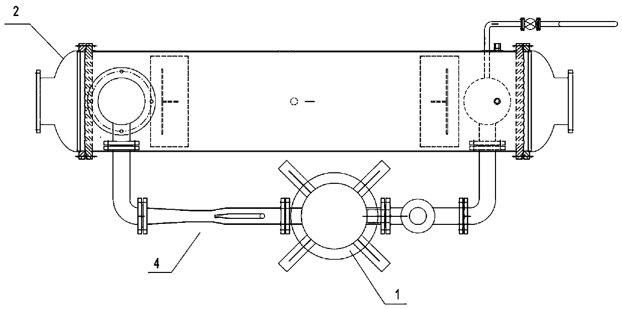
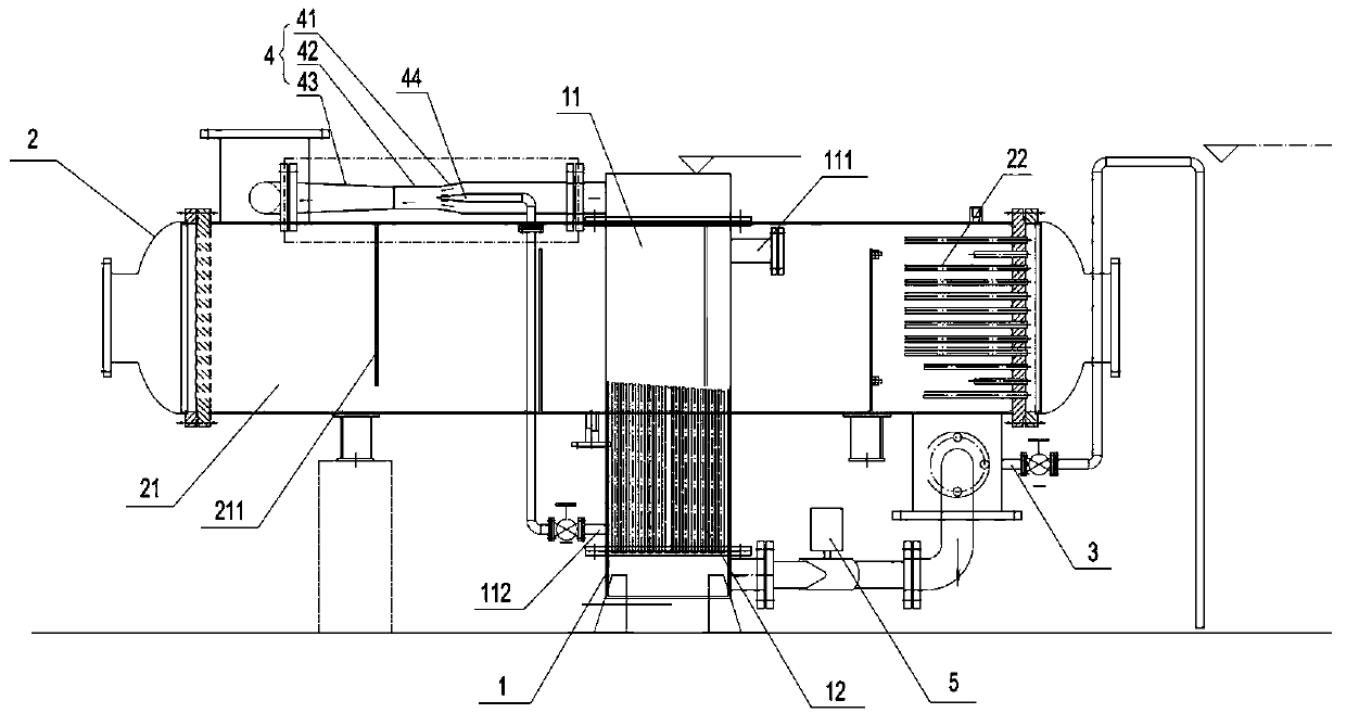
[0023] A steam condensed water residual energy utilization device, comprising a gas-water heat exchanger 1, a water-water heat exchanger 2. The gas-water heat exchanger 1 includes a first heat exchange cavity 11 passing through the first heat exchange cavity 11 The first heat exchange tube group 12 of the first heat exchange cavity 11 is respectively provided with an air inlet 111 and a water outlet 112 at both ends; the water-to-water heat exchanger 2 includes a second heat exchange cavity 21 that penetrates The second heat exchange tube group 22 of the second heat exchange cavity 21; the water outlet end and the water inlet end of the first heat exchange tube group 12 are respectively connected to the water inlet end and the water outlet end of the second heat exchange cavity 21, The water outlet 112 is connected to the water inlet end of the second heat exchange cavity 21; the water outlet end of the second heat exchange cavity 21 is provided with a drain port 3.

[0024] Work...

Embodiment 2

[0027] On the basis of embodiment 1, a water ejector 4 is provided between the water outlet end of the first heat exchange tube group 12 and the water inlet end of the second heat exchange cavity 21, and the water outlet 112 is connected to The water ejector 4. The water ejector 4 first mixes two water bodies with different temperatures and different flow rates into one body, and then passes into the second heat exchange cavity 21, which can effectively ensure the stability of the water circulation and heat exchange effect. Specifically, the water ejector 4 includes a shrink tube 41, a mixing tube 42, and a diffusion tube 43 in sequence along the flow direction of the internal water body. The shrink tube 41 is provided with a nozzle 44, and the water inlet end of the nozzle 44 communicates with each other. The water outlet 112. The water-water ejector 4 gradually reduces the diameter of the fluid to be ejected through the shrink tube 41, and mixes the high-speed ejection fluid...


PUM


Abstract

The invention discloses a steam condensation water complementary energy utilization device, and belongs to the technical field of heat exchange devices. The steam condensation water complementary energy utilization device comprises a gas-water heat exchanger and a water-water heat exchanger; the gas-water heat exchanger comprises a first heat exchange cavity and a first heat exchange pipe set penetrating through the first heat exchange cavity, and the two ends of the heat exchange cavity are provided with an air inlet and an air outlet separately; the water-water heat exchanger comprises a second heat exchange cavity and a second heat exchange pipe set penetrating through the second heat exchange cavity; the water outlet end and the water inlet end of the first heat exchange pipe set communicate with the water inlet end and the water outlet end of the second heat exchange cavity respectively, and a water outlet communicates with the water inlet end of the second heat exchange cavity; and the water outlet end of the second heat exchange cavity is provided with a water draining port. According to the steam condensation water complementary energy utilization device, waste heat and excessive pressure of steam condensation water can be effectively utilized, and then the energy source utilization rate of heat exchange equipment is increased.

Description

Technical field [0001] The invention relates to the technical field of heat exchange devices, in particular to a steam condensate residual energy utilization device. Background technique [0002] Heat exchanger is an energy-saving equipment that realizes heat transfer between materials between two or more fluids at different temperatures. It transfers heat from a higher temperature fluid to a lower temperature fluid, so that the fluid temperature reaches the process The specified index is to meet the needs of process conditions, and it is also one of the main equipment to improve energy efficiency. The heat exchanger industry involves nearly 30 industries such as HVAC, pressure vessels, reclaimed water treatment equipment, chemicals, and petroleum, forming an industrial chain with each other. [0003] However, the energy efficiency of heat exchangers or heat exchange equipment still needs to be improved in some cases. For example, at present, some large-scale air-conditioning sys...

Claims


Application Information

Patent Timeline
Patent Type & Authority Applications(China)
IPC IPC(8): F28D21/00
CPCY02B30/56
Inventor 曹顺发吴乐逊高峰曹晋姚雪峰
Owner 浙江大东吴集团建设有限公司
Why Eureka
Try Eureka