Heat flow identification method based on step response calibration

A technology of step response and identification method, which is applied in the field of back-calculating surface heat flow by calibrating the step response of temperature measurement points inside the structure, can solve the problems of reducing the calculation accuracy of heat flow, increasing the uncertainty of results, and measuring errors, etc. The effect of fast calculation speed, simple and easy calculation method and strong robustness

Active Publication Date: 2019-06-21
HARBIN INST OF TECH
View PDF4 Cites 3 Cited by
  • Summary
  • Abstract
  • Description
  • Claims
  • Application Information

AI Technical Summary

Problems solved by technology

However, the traditional method needs to know the input parameters such as the position of the temperature measuring point, the thermophysical parameters of the material, the structure size and the surface emissivity when calculating the heat flow, and these parameters need to be obtained through experimental measurement, which will increase the uncertainty of the results
In addition, thermocouple temperature measurement will be affected by factors such as signal hysteresis and local heat loss, which will introduce measurement errors and reduce the accuracy of heat flow calculations.

Method used


Image

  • Heat flow identification method based on step response calibration
  • Heat flow identification method based on step response calibration
  • Heat flow identification method based on step response calibration

Examples


Embodiment

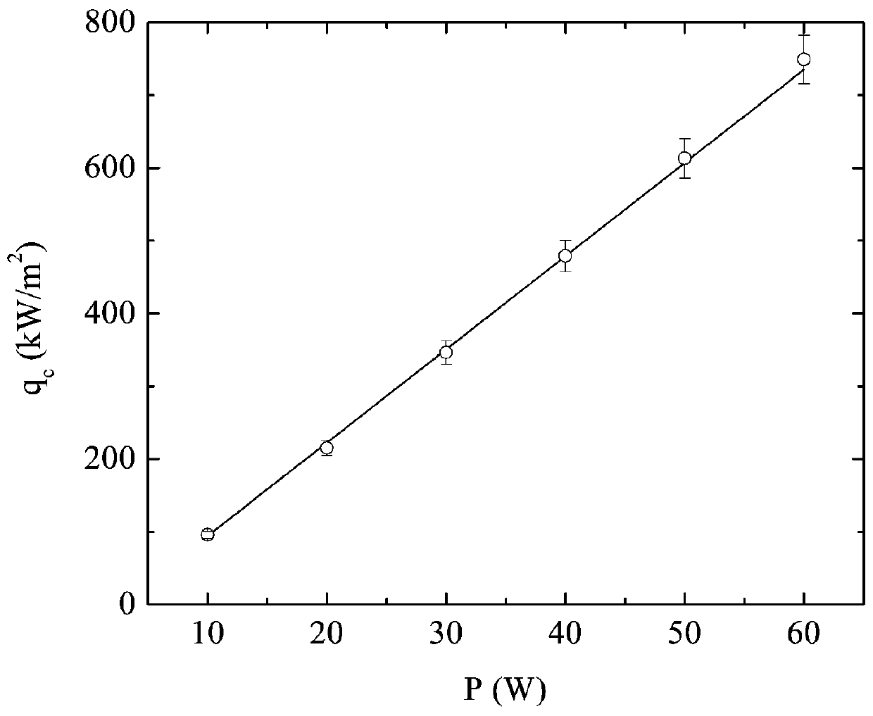
[0102] Taking the step response of laser calibration as an example, the heat flow generated by the laser system (DILAS DL 020R) measured by a Gardon meter (model: 12-600-.79-4-36-20944) has an approximate linear relationship with the power, such as figure 2 As shown, the linear fitting relationship between heat flow and laser power P is:

[0103] q c = 12.815P-33.828 (20).

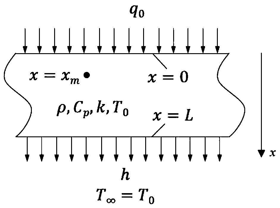
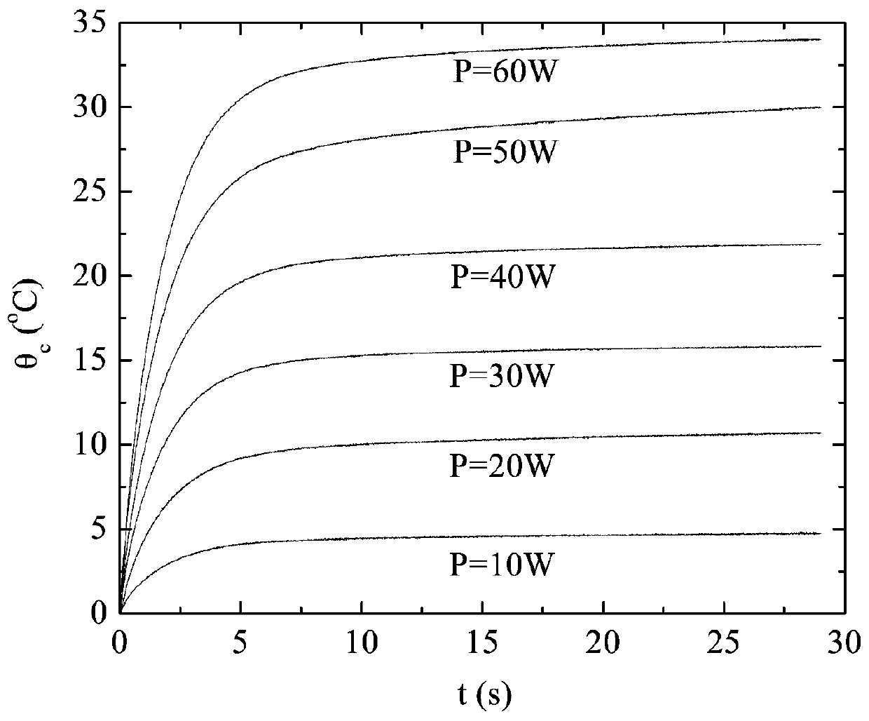
[0104] The side of a cylinder is insulated and the back of the cylinder is water-cooled, and the heat transfer process inside the cylinder satisfies the one-dimensional heat conduction model shown in formula (1). A constant heat flow is applied to the surface of the cylinder by a laser, and a thermocouple is embedded inside the cylinder to measure its temperature response. A constant heat flow is applied to the surface of the cylinder by a laser, and the temperature curves are measured at different output powers, such as image 3 shown.

[0105] for image 3 The temperature measured under each power ...


PUM


Abstract

The invention discloses a heat flow identification method based on step response calibration. The method comprises the following steps: step 1, calibrating step response (t) of a heat conductor; step2, assuming that q (t) is a constant in each t, and setting the component of the ith [ti, t + 1] as qi; step 3, dispersing Y (t) and (t) to obtain Y = Xq; step 4, performing singular value decomposition on X; step 5, performing truncation on the singular value decomposition to obtain Xnew; step 6, replacing X with Xnew, and performing inversion through the matrix to obtain q; step 7, calculating Rand S; step 8, drawing an L curve, and setting an Ns value corresponding to the maximum curvature of the L curve as the optimal singular value number Nopt; and step 9, carrying out noise reduction onthe vi to obtain a step 10, and replacing the vi with the finally obtained heat flow. According to the calibration method and the heat flow identification method provided by the invention, the uncertainty of an identification result can be effectively reduced, and higher heat flow calculation precision is achieved.

Description

technical field [0001] The invention relates to a high-precision identification method for heat flow, in particular to a method for back-calculating surface heat flow through the step response of a temperature measuring point inside a calibration structure. Background technique [0002] For the heat flow measurement in the extreme service environment of the thermal protection system of the re-entry vehicle, the measurement device installed on the surface will bear a greater risk of failure, and it is difficult to achieve a long-term stable measurement of the heat flow on the surface of the structure. On the contrary, the measurement of the internal temperature of the structure has higher reliability and stability, and is easier to realize. Currently, a widely used method is to calculate the surface heat flow by solving the inverse problem model by measuring the temperature at several locations inside the structure. However, the traditional method needs to know the input par...

Claims


Application Information

Patent Timeline
Patent Type & Authority Applications(China)
IPC IPC(8): G06F17/11
Inventor 孟松鹤卓立军易法军许承海金华解维华
Owner HARBIN INST OF TECH
Why Eureka
Try Eureka