Switched reluctance generator converter and control method thereof

A switched reluctance and generator technology, which is applied in the direction of controlling the generator through the change of the magnetic field, can solve the problems of increasing cost, structure and control complexity, increasing the structure and control complexity, and not being able to cover the high requirements of the converter. Achieve the effects of improving operational reliability and power generation efficiency, simplifying the structure, and increasing the boost multiple

Active Publication Date: 2019-06-21
CHINA JILIANG UNIV
View PDF9 Cites 9 Cited by
  • Summary
  • Abstract
  • Description
  • Claims
  • Application Information

AI Technical Summary

Problems solved by technology

[0002] Switched reluctance generators have received more and more attention in recent years, but their high reliability, low cost, and simple and sturdy motor body cannot cover up their high requirements for converters. Without converters, the motor will not work
[0003] The operation of each phase winding of the switched reluctance generator is divided into an excitation stage and a power generation stage, which are carried out in time-sharing. The excitation stage absorbs electric energy, and the power generation stage releases electric energy. Therefore, the shorter the excitation stage time and the faster the excitation current can be established, it is bound to improve the power generation. There are many ways to strengthen the output capacity and excitation. For example, the excitation voltage can be adjusted according to the needs, and the excitation voltage can be increased to strengthen the excitation. This requires a special excitation circuit. At present, most of the excitation circuits and the main inverter circuit The space often needs to be isolated, which will inevitably increase the cost and the complexity of the structure and control
[0004] Moreover, since the excitation circuit is mostly in self-excitation mode, when the current at the input end of the excitation circuit is intermittent, it will cause interference to the output side of the generator. If the current at the output side of the excitation circuit is intermittent, the excitation performance will be greatly reduced. Mode Although the power is stable, the cost of manual maintenance is too high
[0005] Various types of converters must use a large number of switching tubes. Switching loss has become a problem that must be paid attention to in this field at present, which will greatly reduce the conversion efficiency and reliability. It is bound to increase the complexity of the structure and control and reduce the reliability

Method used


Image

  • Switched reluctance generator converter and control method thereof
  • Switched reluctance generator converter and control method thereof

Examples


Embodiment Construction

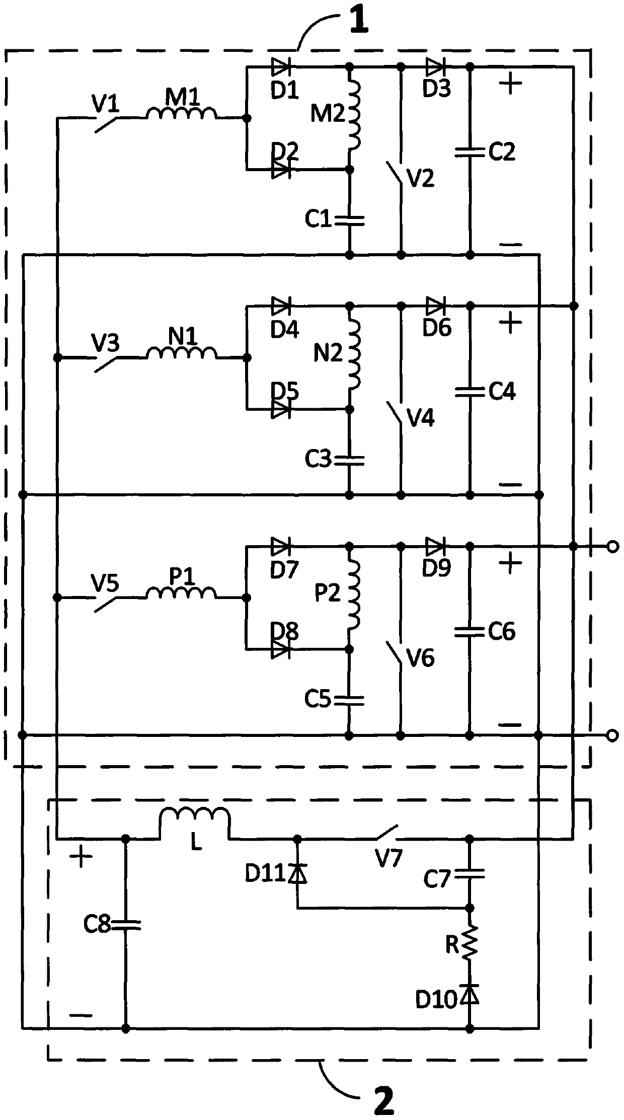
[0023] A switched reluctance generator converter of this embodiment, as attached figure 1 As shown, it is composed of a main converter circuit 1 and a self-excited excitation circuit 2. The output positive terminal of the main converter circuit 1 is connected to the input positive terminal of the self-excited excitation circuit 2, and the output negative terminal of the main converter circuit 1 is connected to the self-excited The excitation circuit 2 has a negative input terminal, the output positive terminal of the self-excitation excitation circuit 2 is connected to the input positive terminal of the main converter circuit 1, and the output negative terminal of the self-excitation excitation circuit 2 is connected to the input negative end of the main converter circuit 1.

[0024] The main converter circuit 1 consists of a first switching tube V1, a second switching tube V2, a third switching tube V3, a fourth switching tube V4, a fifth switching tube V5, a sixth switching tube...


PUM


Abstract

The invention discloses a switched reluctance generator converter and a control method thereof. The converter is composed of a converter main circuit and a self-excitation variable-excitation circuit,and totally comprises a three-phase winding, seven switching tubes, eleven diodes, eight capacitors, an inductor and one resistor; branch windings of each phase winding of the converter main circuitare connected in parallel during excitation of each phase winding, and are automatically connected in series during power generation; an output voltage is increased; the negative electrodes of the converter main circuit and the self-excitation variable-excitation circuit are in a common ground state; input and output currents of the self-excitation variable-excitation circuit are not interrupted during operation, and an output excitation voltage of the self-excitation variable-excitation circuit can be adjusted through a duty ratio of the seventh switching tube; other switching tubes except the seventh switching tube are all in a single pulse wave switching mode; and therefore, the whole converter can be strengthened and diversified in excitation, and is high in input and output electric energy quality, high in output voltage, low in switching loss, simple and convenient to control and suitable for the fields of various switched reluctance generator systems, especially high-speed low-power switched reluctance generator systems.

Description

Technical field [0001] The invention relates to the field of switched reluctance generator systems, in particular to a switched reluctance generator converter with self-enhanced variable excitation, common ground for excitation and power generation, low switching loss and high power quality, and a control method thereof. Background technique [0002] Switched reluctance generators have received more and more attention in recent years, but their high reliability, low cost, simple and sturdy motor body cannot conceal their high requirements for the converter, and the motor will not work without the converter. [0003] Each phase of the switched reluctance generator is divided into an excitation phase and a power generation phase, which are carried out in time. The excitation phase absorbs electric energy and the power generation phase releases electric energy. Therefore, the shorter the excitation phase time and the excitation current can be established as soon as possible, it is boun...

Claims


Application Information

Patent Timeline
Patent Type & Authority Applications(China)
IPC IPC(8): H02P9/30
Inventor 孙冠群
Owner CHINA JILIANG UNIV
Why Eureka
Try Eureka