
Lock opening and closing mechanism for bottle blowing machine die frame

A locking mechanism and a bottle blowing machine technology, applied in the field of bottle blowing, can solve the problems of large reverse holding force, serious accident, large holding force, etc., and achieve the reduction of impact and noise, reliable operation, and no deviation in size and shape and position. sensitive effect

Active Publication Date: 2019-06-25
JIANGSU NEWAMSTAR PACKAGING MACHINERY
View PDF6 Cites 0 Cited by
  • Summary
  • Abstract
  • Description
  • Claims
  • Application Information

AI Technical Summary

Problems solved by technology

Existing embodiments of this technical solution adopt a structure in which the fixed claw buckle faces outward and the movable claw buckle faces inward, which has the following defects: 1) The centrifugal inertial force of the movable claw faces the direction of the two claws to release, in order to ensure the bottle blowing process The two claws in the middle can be effectively interlocked, and a large reverse holding force must be exerted on the movable claws; 2) If the bottle bursts (referring to the rupture of the preform) during the blowing process, the high-pressure airflow leaking from the blowing cavity may make the two Claw tripped, causing more serious accidents
However, the existing claw-type opening and closing technical solutions still have defects such as the large holding force required for effective interlocking of the two claws and the risk of bottle explosion, and the unlocking and locking are both driven by guide rails, which is still relatively complicated and needs further improvement

Method used


Image

  • Lock opening and closing mechanism for bottle blowing machine die frame
  • Lock opening and closing mechanism for bottle blowing machine die frame
  • Lock opening and closing mechanism for bottle blowing machine die frame

Examples


Embodiment Construction

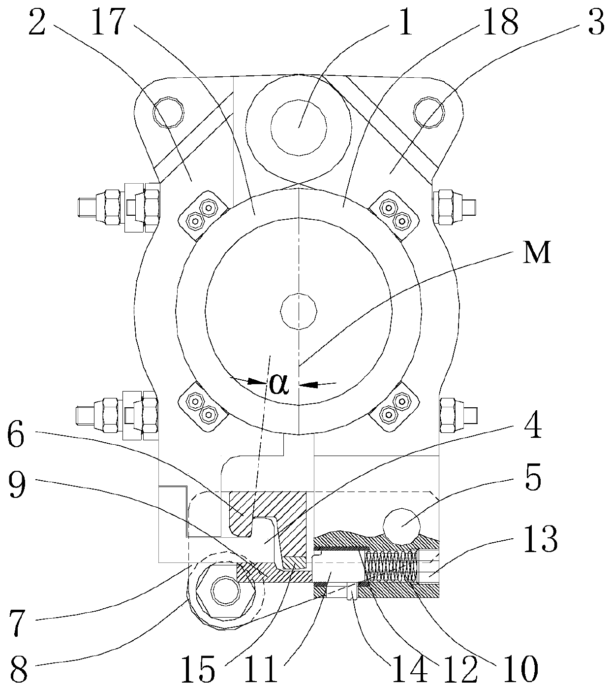
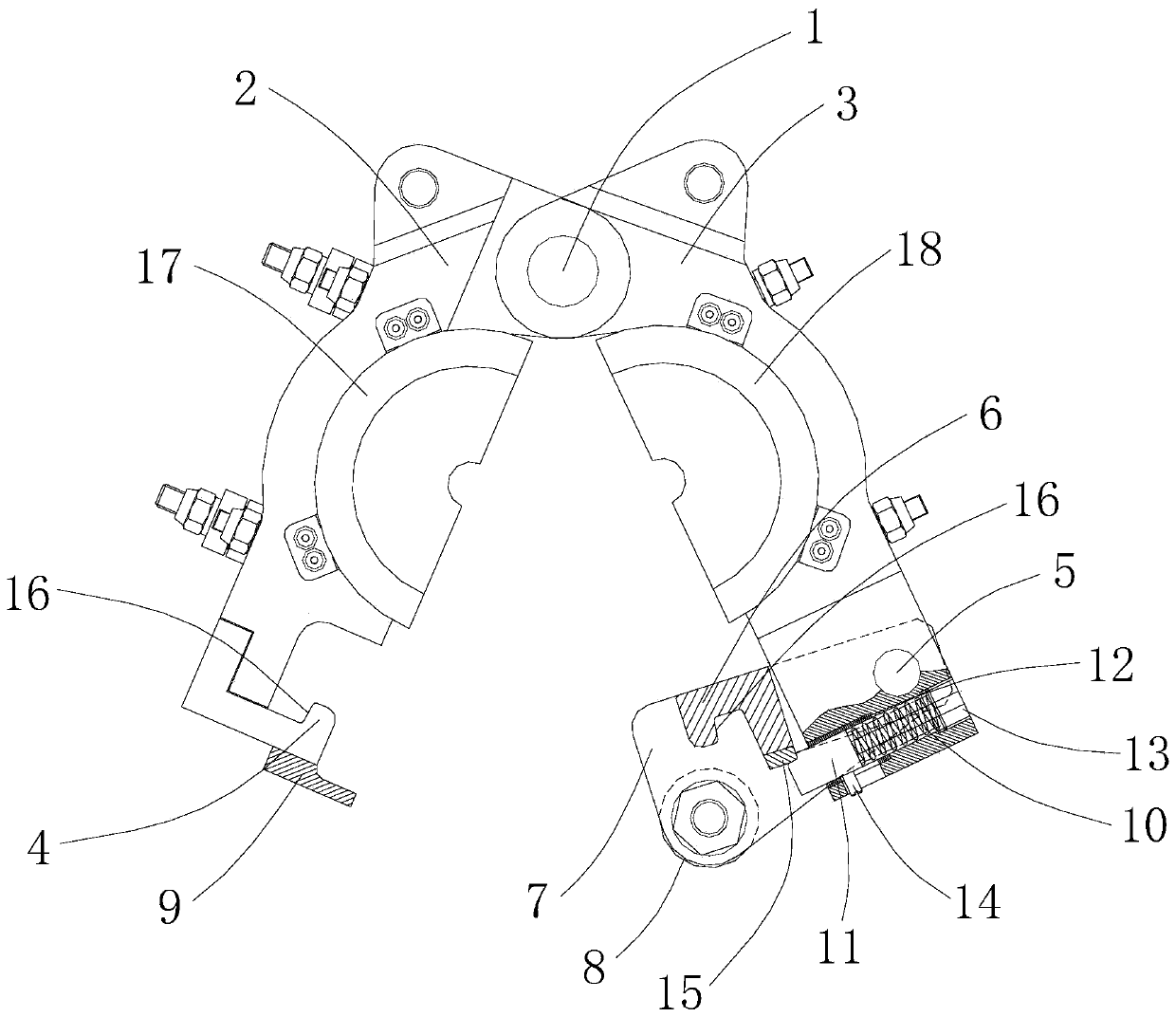
[0032] The technical solution of the present invention will be further described below in conjunction with the accompanying drawings.

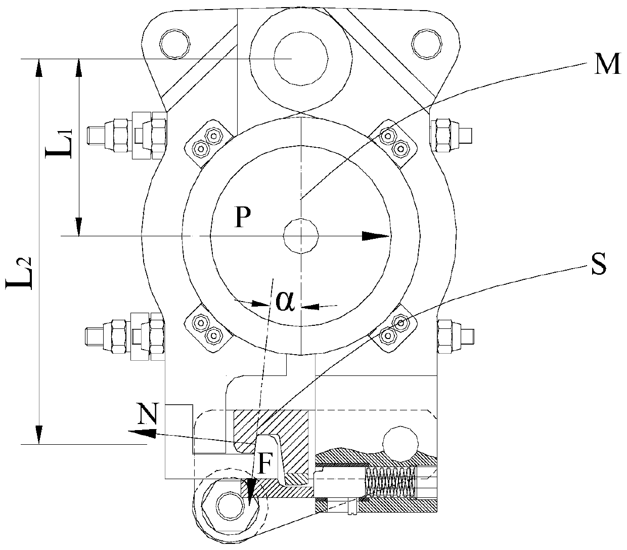
[0033] see Figure 1-2 As shown, the above-mentioned opening and closing mechanism of the mold frame of the bottle blowing machine, the bottle blowing machine includes a frame, and the first parts for opening and closing molds that are arranged on the frame and are used to cooperate with each other can rotate around the first axis line 1 respectively. Formwork 2 and second formwork 3, the first mold 17 and the second mold 18 that are respectively arranged on the first formwork 2 and the second formwork 3 inside, the first mold 17 and the second mold 18 are mutual when mold closing. Enclosed to form a bottle blowing cavity. In this embodiment, the first axis line 1 extends along the vertical direction.

[0034] The above-mentioned opening and closing mechanism of the blow molding machine mold frame includes a fixed claw 4 arranged on the firs...


PUM


Abstract

The invention discloses a lock opening and closing mechanism for a bottle blowing machine die frame. The mechanism comprises a first elastic part which is arranged on a second die frame and is used for driving a movable claw to rotate far away from a bottle blowing chamber, an elastic locking mechanism which is elastically telescopically arranged on the second die frame and is ejected to stop themovable claw to rotate far away from the bottle blowing chamber, and a control block which is arranged on a fixed claw and is used for propping the elastic locking mechanism to contract and be far away from the movable claw; when a first die frame and the second die frame are rotated to close a die, the elastic locking mechanism is propped through the control block; the movable claw is rotated faraway from the bottle blowing chamber and is hooked and locked to the fixed claw; and when the first die frame and the second die frame are rotated to open the die, the control block is far away fromthe elastic locking mechanism, and the movable claw is rotated to be close to the bottle blowing machine and is separated from the fixed claw, defects of holding force for building of the two claws inan existing claw type lock opening and closing structure and risk of bottle breaking can be overcome; and the two die frames can be interlocked without being driven through guide rails.

Description

technical field [0001] The invention relates to the technical field of bottle blowing, in particular to an opening and closing mechanism for a mold base of a bottle blowing machine. Background technique [0002] For the rotary blow molding machine in which the two side mold frames rotate during the mold opening and closing process, the existing opening and closing technical solutions for the two side mold frames are as follows: [0003] Bolt-type opening and closing lock: In this technical scheme, a bolt that can move up and down is installed on one side formwork, and a bolt hole that cooperates with the bolt is arranged on the other side formwork. During the mold clamping and bottle blowing process, the pin on one side mold base is inserted into the pin hole on the other side mold base to prevent the relative rotation (locking) of the two side mold bases; The latch exits the latch hole on the other side formwork, allowing the relative rotation (unlocking) of the two side f...

Claims


Application Information

Patent Timeline
Patent Type & Authority Applications(China)
IPC IPC(8): B29C49/56
CPCY02P40/57
Inventor 钱志良
Owner JIANGSU NEWAMSTAR PACKAGING MACHINERY
Learn More