Industrial automatic conveying device

An industrial automation and conveying device technology, applied in conveyors, conveyor objects, mechanical conveyors, etc., can solve the problems of difficulty and increase of operators, and achieve the effect of reducing impact force, Fangbai operation, and protecting objects.

Inactive Publication Date: 2019-06-25
XIAN LIYUAN INTELLIGENT TECH
View PDF1 Cites 0 Cited by
  • Summary
  • Abstract
  • Description
  • Claims
  • Application Information

AI Technical Summary

Problems solved by technology

[0002] With the continuous development of people's modern science and technology, more and more items are used more and more frequently in people's lives. With the increase in frequency of use, the production of these items has entered the stage of mass production. Mass production means The increase in production quantity requires an assembly line. The transmission device is indispensable on the assembly line. The industrial automatic transmission mechanism proposed by the application number 201410758279.X is equipped with a manipulator through the floor and on the floor, and a remote control. , the device can be commanded remotely to transfer parts. This device can save a lot of manpower, which can greatly improve production efficiency and automation. However, due to the increase in mass production, ordinary machines and operators cannot bear the load. Therefore, We need intermittent transmission, so we propose an industrial automation transmission device

Method used


Image

  • Industrial automatic conveying device
  • Industrial automatic conveying device
  • Industrial automatic conveying device

Examples


Embodiment Construction

[0017] The following will clearly and completely describe the technical solutions in the embodiments of the present invention with reference to the accompanying drawings in the embodiments of the present invention. Obviously, the described embodiments are only some, not all, embodiments of the present invention.

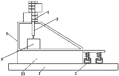
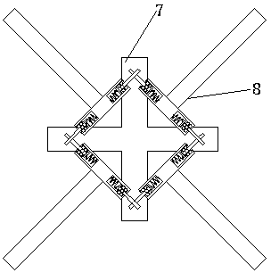
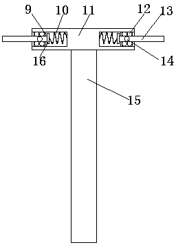
[0018] refer to Figure 1-4 , an industrial automation transmission device, including a device base 1, the top of the device base 1 is fixedly installed with a storage seat 23 and a shock absorbing receiving seat 2, and the top of the storage seat 23 is fixed with a sliding slope 5, and the sliding slope 5 is a cavity structure, and the cross section of the sliding slope 5 is trapezoidal, the trapezoidal hypotenuse faces upward, the shock absorbing receiving seat 2 is arranged on the top of the device base 1 near the side of the trapezoidal short side, and the inner wall of the bottom end of the sliding slope 5 is fixedly equipped with a motor 6, The output shaft of ...


PUM


Abstract

The invention discloses an industrial automatic conveying device. The industrial automatic conveying device comprises a device base, a placing seat and a damping receiving seat are fixedly arranged atthe top end of the device base, a sliding slope is fixedly arranged at the top end of the placing seat, the sliding slope is of a cavity structure, the cross section of the sliding slope is trapezoid, the trapezoid inclined edge is upward, the damping receiving seat is arranged on the side, close to the trapezoid short edge, of the top end of the device base, a motor is fixedly installed on the inner wall of the bottom end of the sliding slope, the output shaft of the motor is welded to a rotating rod, a round through hole is formed in the top end of the sliding slope, the rotating rod is rotationally connected with the sliding slope at the round through hole, the top end of the sliding slope is provided with an intermittent conveying device, and the intermittent conveying device comprises a cross rotating rod and a separating device. Compared with an existing product, the industrial automatic conveying device has the advantages that on one hand, the conveying frequency can be changed, operation of a user is facilitated, and on the other hand, the impact force of articles conveying can be effectively relieved to protect the articles.

Description

technical field [0001] The invention relates to the technical field of conveying devices, in particular to an industrial automation conveying device. Background technique [0002] With the continuous development of people's modern science and technology, more and more items are used more and more frequently in people's lives. With the increase in frequency of use, the production of these items has entered the stage of mass production. Mass production means The increase in production quantity requires an assembly line. The transmission device is indispensable on the assembly line. The industrial automatic transmission mechanism proposed by the application number 201410758279.X is equipped with a manipulator through the floor and on the floor, and a remote control. , the device can be commanded remotely to transfer parts. This device can save a lot of manpower, which can greatly improve production efficiency and automation. However, due to the increase in mass production, ordi...

Claims


Application Information

Patent Timeline
IPC IPC(8): B65G35/00B65G47/00
Inventor 王翊婷
Owner XIAN LIYUAN INTELLIGENT TECH
Why Eureka
Try Eureka