Facility and method for siphon water changing in reservoir by using rain-flood resources

A siphon and rainwater technology, applied in water conservancy engineering equipment, water conservancy projects, general water supply conservation, etc., can solve the problem that the sand and gravel layer at the bottom of the reservoir cannot be replaced, and achieve the effect of energy saving

Active Publication Date: 2019-06-25
NANJING HYDRAULIC RES INST
View PDF5 Cites 9 Cited by
  • Summary
  • Abstract
  • Description
  • Claims
  • Application Information

AI Technical Summary

Problems solved by technology

If water pumps are used to pump water, a lot of manpower, equipment, energy and funds will be spent. If the discharge of water from the bottom hole of the emb

Method used


Image

  • Facility and method for siphon water changing in reservoir by using rain-flood resources
  • Facility and method for siphon water changing in reservoir by using rain-flood resources
  • Facility and method for siphon water changing in reservoir by using rain-flood resources

Examples


Embodiment 1

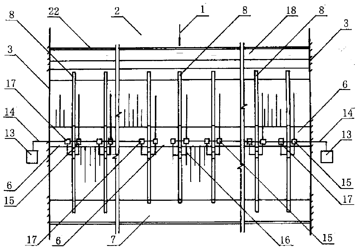
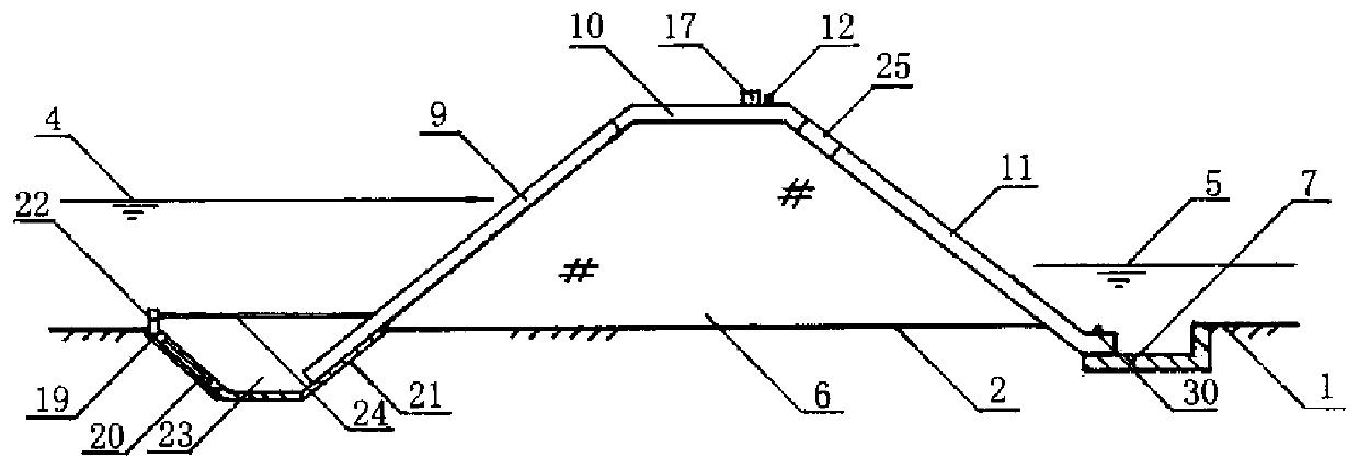
[0028] like Figure 1-4 Shown, a kind of reservoir utilizes the structure of the facility of stormwater resource siphon to exchange water as follows: a sump 18 is set at the upstream dam foot of the reservoir dam 6, an apron 7 is established at the downstream dam foot of the dam 6, the sump and The bottom of the apron is lower than the riverbed surface and is in a concave form. A row of siphon pipes 8 are arranged on the embankment 6, and all of these siphon pipes 8 are circular pipes of equal diameter, and all of these siphon pipes 8 are in the shape of "︹". The siphon pipe 8 is composed of a water inlet pipe 9 , a hump pipe 10 , a diverter 25 and a water outlet pipe 11 connected in sequence from upstream to downstream. The water inlet pipeline 9 is installed on the upstream dam slope of the embankment 6 , and the water inlet of the water inlet pipeline 9 is located at the bottom in the sump 18 . The hump pipeline 10 is installed on the crest of the embankment 6, the divert...

Embodiment 2

[0033] This embodiment provides a method for a reservoir to use rainwater resources for siphon water exchange, including the following steps:

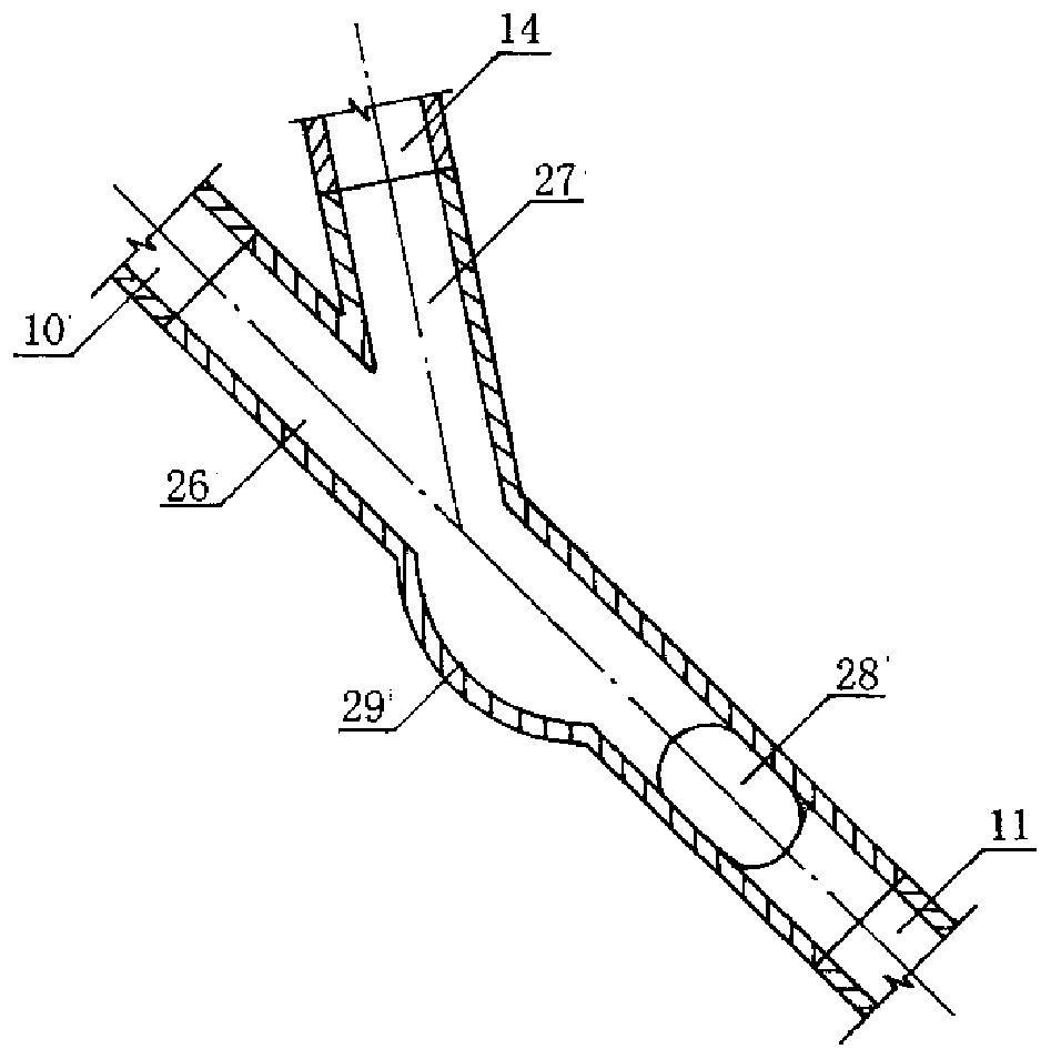
[0034] (1) On the embankment 6, several water inlet pipes 9 spaced from each other are installed along the upstream dam slope, the water inlets of these water inlet pipes 9 are installed at the bottom in the sump 18, and several water inlet pipes 9 spaced apart from each other are installed along the top of the dam. Root hump pipes 10, diverters 25 are installed at the ends of these hump pipes 10, several outlet pipes 11 spaced apart from each other are installed along the downstream dam slope, and the outlets of these outlet pipes 11 are all located at the bottom of the apron 7, These water inlet pipes 9 , hump pipes 10 , diverters 25 and water outlet pipes 11 are respectively connected in sequence from upstream to downstream to form a row of parallel siphon pipes 8 . Air intake interface 12 is all installed in the through hole of all...


PUM


Abstract

The invention discloses a facility and a method for siphon water changing in a reservoir by using rain-flood resources. The facility is characterized in that a collecting pool is arranged at the upstream dam toe of a reservoir dam, an apron is arranged at the downstream dam toe of the dam, a row of siphons are installed on the dam, and each siphon is connected by a water inlet pipe, a hump pipe, adrainage device and a water outlet pipe in sequence from the upstream to the downstream. When an upstream water level is higher than a downstream water level, control cabinets start water storage pools and water pumps to deliver water to the drainage devices, and the drainage devices initiate the siphons to siphon and release water. The facility uses the rain-flood resources to change water for the reservoir in a flood season, and negative pressure sensors and water outlet sensors are arranged on the siphons for intelligent control, so that the facility has the characteristics of safety, reliability, simple structure, all-weather siphoning water changing, large discharge flow, low energy consumption, easy operation, intelligent control and the like, and is an advanced water conservancy and environmental protection facility.

Description

technical field [0001] The invention relates to the fields of water conservancy and environmental protection, in particular to a facility for siphoning water from a reservoir using rainwater resources. Background technique [0002] At present, when the reservoir replaces the water in the reservoir, water pump equipment is often used to pump water or open the bottom hole of the embankment to discharge water. If adopt water pump to draw water, need spend a large amount of manpower, equipment, energy and fund, if adopt embankment bottom hole to discharge water, can only replace the local water in the reservoir, can't replace the water in the gravel layer at the bottom of the reservoir again. Contents of the invention [0003] In view of the shortcomings of the above situation, the present invention proposes a facility for siphoning water from rainwater and flood resources in the reservoir. A siphon is installed on the embankment to replace the water in the bottom of the reser...

Claims


Application Information

Patent Timeline
IPC IPC(8): E02B1/00E02B3/00
CPCE02B7/10E02B7/18E03B3/02Y02A20/108
Inventor 王宗志刘克琳程亮姜蓓蕾叶爱玲郭照河张明芳刘建光汪哲荪杜慧华王坤詹新焕
Owner NANJING HYDRAULIC RES INST
Why Eureka
Try Eureka