Frequency configuration method for photoelectric detector frequency response measurement

A photodetector and frequency configuration technology, applied in the field of optoelectronics, can solve the problems of difficult to achieve broadband measurement, measurement bandwidth limitation, measurement range limitation, etc., and achieve the effect of self-calibration measurement

Active Publication Date: 2019-06-25
UNIV OF ELECTRONIC SCI & TECH OF CHINA
View PDF9 Cites 2 Cited by
  • Summary
  • Abstract
  • Description
  • Claims
  • Application Information

AI Technical Summary

Problems solved by technology

The frequency-shift heterodyne method uses a two-tone modulation signal and a frequency-shift signal to beat the frequency, and measures the required sideband amplitude to obtain the frequency response of the photodetector. The measurement result is not affected by the frequency response and bias of the electro-optical conversion device, but Its measureme

Method used


Image

  • Frequency configuration method for photoelectric detector frequency response measurement
  • Frequency configuration method for photoelectric detector frequency response measurement
  • Frequency configuration method for photoelectric detector frequency response measurement

Examples


Embodiment

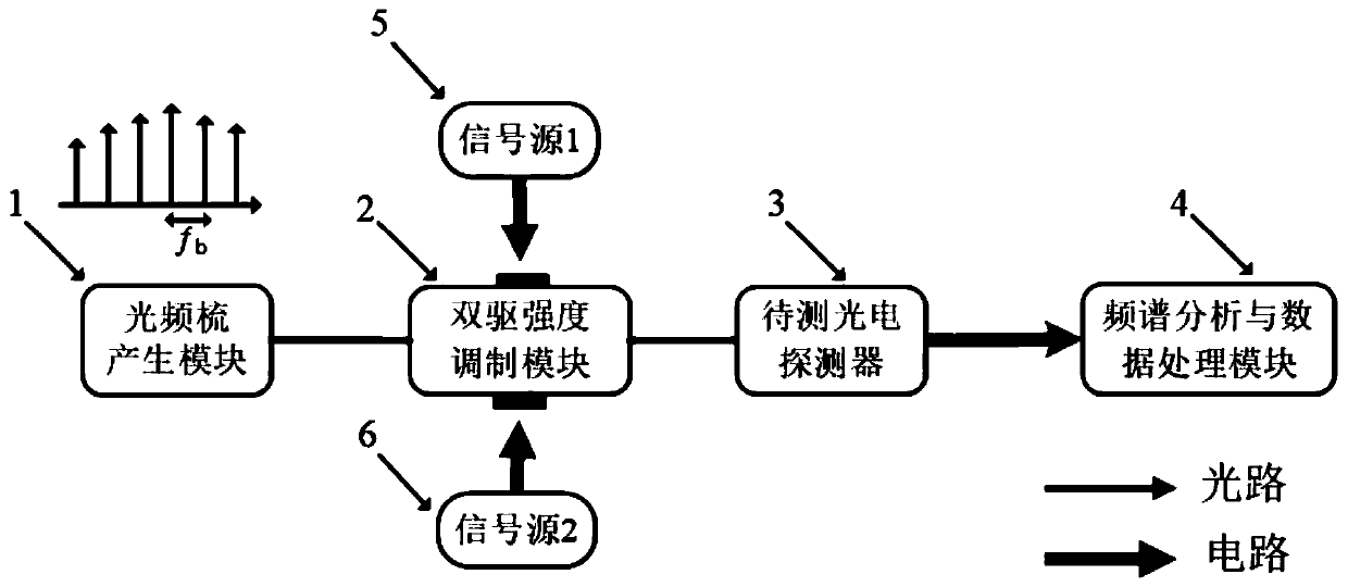
[0059] In this embodiment, the measurement range of the photodetector to be tested is 15 GHz, and the measurement resolution is 0.5 GHz. The optical frequency comb generation module uses a mode-locked laser with adjustable frequency interval, and the dual-drive intensity modulation module uses a Mach-Zehnder electro-optical intensity modulator. The sinusoidal microwave signals output by signal source 1 and signal source 2 are connected to the dual-drive intensity modulation module On the driving electrode, the optical signal output by the electro-optical intensity modulation module is photoelectrically converted in the photodetector to form an electrical signal, which is analyzed and measured by the spectrum analysis and data processing module.

[0060] Set the repetition frequency f of the optical frequency comb generation module b =(M+1)f step =(10+1)×0.5GHz=5.5GHz. In the frequency domain, the measurement range of the photodetector to be tested is divided into 0-5.5GHz, 5...


PUM


Abstract

The invention relates to a frequency configuration method for photoelectric detector frequency response measurement. According to the method, an optical frequency comb generating module, a double-drive intensity modulation module, a photoelectric detector to be tested, a spectrum analysis and data processing module, a signal source A and a signal source B are adopted, wherein the optical frequencycomb generating module, the double-drive intensity modulation module, the photoelectric detector to be tested and the spectrum analysis and data processing module are connected with one another sequentially, and the signal source A and the signal source B are connected with the driving electrode of the double-drive intensity modulation module; and optical frequency comb signals generated by the optical frequency comb generating module are simultaneously modulated by the signal source A and the signal source B in the double-drive intensity modulation module. According to the frequency configuration method for photoelectric detector frequency response measurement of the invention, the repetitive frequency of the optical comb generating module and the frequencies of the two signal sources are configured, so that the segmental measurement and inter-segment splicing of the frequency response of the photoelectric detector are realized, and ultra-wide-frequency-range photoelectric detector frequency response measurement can be realized by means of low-frequency microwave driving.

Description

technical field [0001] The invention belongs to the measurement technology of characteristic parameters of optoelectronic devices in the field of optoelectronic technology, and in particular relates to a frequency configuration method for frequency response measurement of photodetectors. Background technique [0002] High-speed photodetectors are important components in optical fiber communication systems, optical signal processing links, and ROF systems. The frequency response characteristics of photodetectors during photoelectric conversion are key indicators to measure their performance, and also directly affect optical fiber communication. The transmission, processing and detection capabilities of signals in the system. Accurate measurement of the frequency response of broadband photodetectors plays an important role in optimizing device operating parameters and system performance. [0003] At present, the methods for measuring photodetectors can be divided into all-lig...

Claims


Application Information

Patent Timeline
IPC IPC(8): G01D18/00
Inventor 张尚剑刘胜鑫王梦珂张雅丽刘永
Owner UNIV OF ELECTRONIC SCI & TECH OF CHINA
Why Eureka
Try Eureka