Fixing structure for fixing lower end of annular fuel rod and lower tube seat

A fixed structure and fuel rod technology, applied in the assembly of fuel elements, fuel elements, reactor fuel elements, etc., can solve the problems of blockage of fuel rod flow channels, threats to fuel rod safety, and inability to maintain the cooling capacity of fuel rods. Cooling capacity, effect of increasing flow path area

Active Publication Date: 2019-06-25
CHINA INSTITUTE OF ATOMIC ENERGY
View PDF5 Cites 0 Cited by
  • Summary
  • Abstract
  • Description
  • Claims
  • Application Information

AI Technical Summary

Problems solved by technology

With the operation of the reactor, tiny impurities are likely to appear in the main system, for example, wastes left in the manufacturing process of the internal components of the pressure vessel or in the main circuit piping, or corrosion products formed during the operation of the reactor, etc., which can easily cause fuel The blockage of the flow channel of the rod, and the center hole of the lower end plug is the only water inlet hole of the internal flow channel. If the water inlet hole of the lower end plug is blocked, the flow rate of the inner flow channel of the annular fuel rod will be reduced, and the sufficient cooling capacity of the fuel rod cannot be maintained, threatening Fuel Rod Safety

Method used


Image

  • Fixing structure for fixing lower end of annular fuel rod and lower tube seat
  • Fixing structure for fixing lower end of annular fuel rod and lower tube seat

Examples


Embodiment Construction

[0037] The present invention will be described in further detail below in conjunction with the accompanying drawings and specific embodiments.

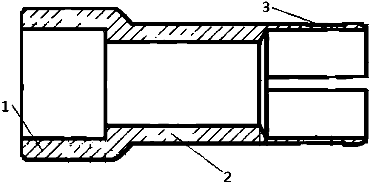
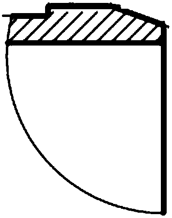
[0038] The structure of the present invention fixes the lower end of the annular fuel rod and the lower pipe seat, and the fixing structure is a central through hole of an integral structure composed of the connecting part 1 of the lower end plug of the annular fuel rod, the transition section 2 and the connecting part 3 of the lower pipe seat. The connecting part 1 is used for connecting the transition section 2 and the lower end plug of the annular fuel rod, and the connecting part 3 is used for connecting the transition section 2 and the lower nozzle seat. The inner diameter of the connecting part 1 is larger than that of the transition section 2, and the fixed structure forms a stepped surface on the inner wall at the junction of the connecting part 1 and the transition section 2; at the junction of the connecting part 1 and the tr...


PUM


Abstract

The invention belongs to the technical field of nuclear fuels, and concretely relates to a welding structure for welding the inner cladding and the end plug of an annular fuel rod. The welding structure includes an inner cladding welding step, a mother tube and an outer cladding welding step, and the three parts form a hollow through tube structure; the step of the inner cladding welding step is an annular protrusion along the inner diameter direction and is used for being welded to the inner cladding of the annular fuel rod; and the step of the outer cladding welding step is an annular projection along the outer diameter direction, and is used for being welded to the outer cladding of the annular fuel rod. A welding point is arranged in the central hole of the annular fuel rod through thesteps of the inner cladding and end plug welding structure, so projections affecting a channel for a coolant to flow in are difficult to form thereby machining is not needed after the completion of welding, and the damage probability of the fuel rod is reduced. The welding structure is suitable for nondestructive test standards of welds in an inner cladding and end plug welding manner, and can ensure the welding quality by radiographic testing and improve the safety of the annular fuel rod.

Description

technical field [0001] The invention belongs to the technical field of nuclear fuel, and in particular relates to a fixing structure for fixing the lower end of an annular fuel rod and a lower pipe seat. Background technique [0002] In the current fuel assembly design, the fuel rod is clamped by the positioning grid and fixed between the upper and lower nozzles, and there is a certain gap between the lower end plug of the fuel rod and the lower nozzle. With the operation of the reactor, the positioning grid becomes loose, and the clamping force is weakened, which is not enough to fix the fuel rods, and the fuel rods will fall. During the collision between the fuel rod lower end plug and the lower tube seat, the fuel rod may be threatened. Integrity, increasing the probability of fuel rod failure. In addition, when the spacer grid loses its clamping force, the fuel rods falling on the lower pipe seat may move up and down under the action of the water flow lifting force, whi...

Claims


Application Information

Patent Timeline
Patent Type & Authority Applications(China)
IPC IPC(8): G21C3/12G21C3/322G21C3/33
CPCY02E30/30
Inventor 史宝磊何晓军刁均辉季松涛邹远方张爱民高永光
Owner CHINA INSTITUTE OF ATOMIC ENERGY
Why Eureka
Try Eureka