Eyeball continuity measurement method and eyeball continuity measurement device

A technology of measuring device and measuring method, which is applied in the direction of eye testing equipment, ophthalmoscope, eye examination, etc., and can solve problems such as difficult observation of eyeball physiological parameters or image changes

Inactive Publication Date: 2019-06-28
UBIQUITY BIOMEDICAL CORP
View PDF5 Cites 1 Cited by
  • Summary
  • Abstract
  • Description
  • Claims
  • Application Information

AI Technical Summary

Problems solved by technology

[0004] In addition, due to the self-regulation mechanism of the eyes, the physiological parameters or images after changing postures may be compensated and cannot be observed within the time of medical personnel moving and setting the equipment, so the existing eye scanning equipment is even more difficult to observe To the changes of eyeball physiological parameters or images in the process of subject's posture transformation

Method used


Image

  • Eyeball continuity measurement method and eyeball continuity measurement device
  • Eyeball continuity measurement method and eyeball continuity measurement device
  • Eyeball continuity measurement method and eyeball continuity measurement device

Examples


no. 1 example

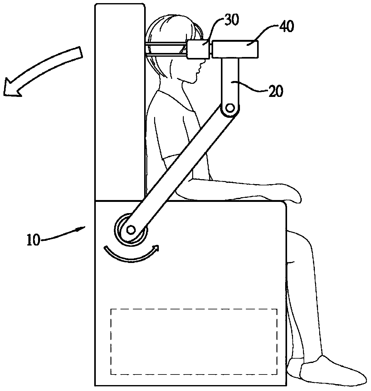
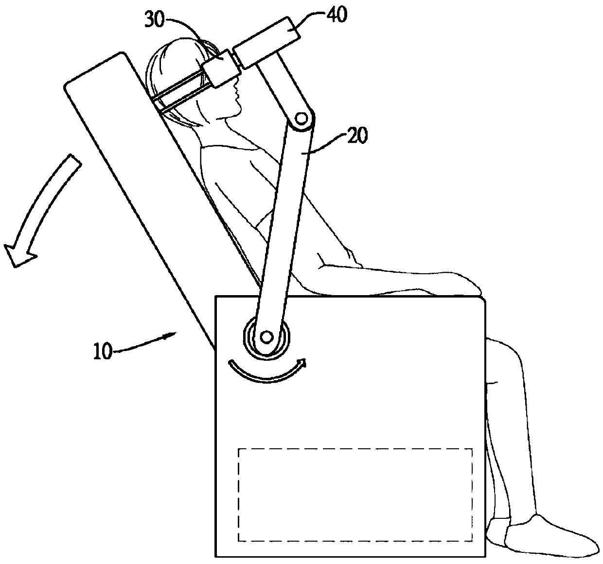
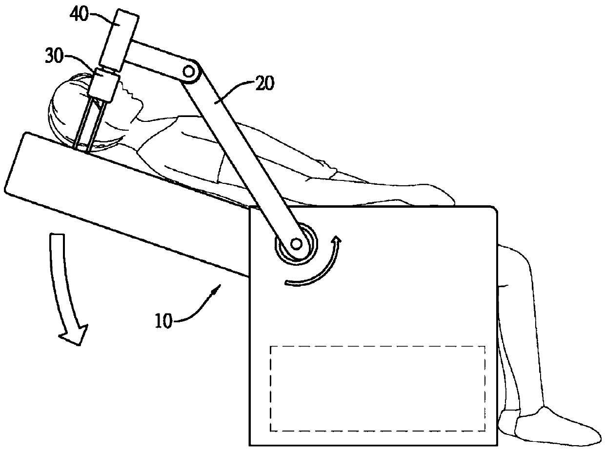
[0080] The first embodiment: seat + eye scanning instrument + eye tracking system + head positioning device + linkage combination mechanism

[0081] See Figure 1 to Figure 3 As shown, at the beginning of the examination, the subject first puts on a goggles 30 (head positioning device) with a magnet (first magnetic attraction) and sits on the seat 10 (base). The goggles 30 are not attached In addition to the brow bone and the bridge of the nose, there is an adjustable elastic band that goes around the back of the subject’s head to enhance stability. The seat 10 has a multi-joint arm 20 (linkage combination mechanism) on the side, and one end of the arm 20 is connected with the rotation axis of the seat 10, so when the seat 10 tilts backward, the same part will drive the multi-joint arm 20 rotates, the other end of the arm 20 is screwed to a probe 40 (eye scanning instrument), which belongs to a set of hand-held parts of an optical coherent tomography system whose main body is ins...

no. 2 example

[0082] Second embodiment: seat + eye scanning instrument + eye tracking system + head positioning device

[0083] At the beginning of the examination, the subject sits on the seat (base), and the headrest of the seat has a hood (head positioning device) that can be adjusted to fit different heights. The subject wears the hood It can be further fixed by using an adjustable elastic band around the chin after it is mounted. The hood also has a three-dimensional micro-motor platform (scanning guide device) at the eye position, which can clamp the fundus camera (eye scanning instrument) On the motor platform, both the motor platform and the fundus camera are connected to the medical personnel's control computer (control system), so the image of the fundus camera can be selected by the software of the eye tracking system to select the scanning position to feed back to the micro motor platform. The camera makes small-scale three-dimensional corrections. After everything is ready, the m...

no. 3 example

[0084] The third embodiment: seat + eye scanning instrument + eye tracking system + linkage combination mechanism

[0085] At the beginning of the examination, the subject sits on the seat (base). There is a set of single cantilever gantry structure (linkage combination mechanism) beside the seat. Medical personnel can fix the ultrasonic probe (eye scanning instrument) on the single cantilever gantry. On the micro-motor platform (scanning guide device) on the structure. The front end of the ultrasonic probe has a soft cushion, its shape can correspond to the contour of the human eye so as to fit the eye position of the subject, and a set of infrared distance sensors (eye tracking system) are installed inside the probe to transmit The infrared light reflected back to the sensor can get the distance from the eye surface of the subject. The ultrasonic system and the single cantilever gantry structure are both connected to the medical personnel's control computer (control system), s...


PUM


Abstract

The invention provides an eyeball continuity measuring method and an eyeball continuity measuring device. According to the method, the posture of a subject is changed in the measurement process, so that the eyeball scanning instrument can continuously measure the change of physiological parameters or images of eyeballs under different postures of the subject, and the continuous measurement not only comprises the instant variation generated under different postures, but also can comprise the variability of time; therefore, the implicit information amount of the obtained information has diversified characteristics; in addition, the information obtained in the one-time measurement process is much richer than that obtained by a single screenshot mode in the prior art; and the data accumulationis much faster than that in the prior art, so that the establishment of a database platform for big data analysis is facilitated, artificial intelligence deep learning is suitable for analysis, and the discovery of early-stage diseases and the like is facilitated.

Description

Technical field [0001] The invention relates to a method and a device for continuously measuring physiological parameters or images of the eyeball. Background technique [0002] In the prior art, when measuring physiological parameters of the eyeball (for example, intraocular pressure) or images (for example, retinal images), a desktop optical coherence tomography (OCT) is often used, and the subject places his chin It is placed on the positioning seat of the optical coherent tomography scanner, and the eyeball physiological parameters or images are measured in a sitting or standing position. In addition, there are also doctors who make the subject lie on their back or side on the hospital bed, and use a handheld optical coherent tomography scanner or ophthalmoscope to measure the physiological parameters of the subject's eyes when lying on their back or side. Or image. [0003] However, no matter what the aforementioned method is, it is to allow the subject to perform the measur...

Claims


Application Information

Patent Timeline
IPC IPC(8): A61B3/10A61B3/12A61B3/113A61B3/14A61B8/10
Inventor 赖弘基马德伦俞力平李向晴
Owner UBIQUITY BIOMEDICAL CORP
Why Eureka
Try Eureka