Grain screening machine with scraping plate impurity removing structure

A technology of screening machine and scraper, which is applied in the direction of sieving, solid separation, grille, etc., can solve the problems of affecting production, different impurity and water content, and blockage of drying surface, so as to save labor, have strong practicability, The effect of increasing production yield

Pending Publication Date: 2019-06-28
ANHUI VISION OPTOELECTRONICS TECH
View PDF0 Cites 0 Cited by
  • Summary
  • Abstract
  • Description
  • Claims
  • Application Information

AI Technical Summary

Problems solved by technology

[0002] At present, the sieves for removing impurities in grains are cylinder sieves and vibrating screens. Due to the low output of cylinder sieves, the impurity removal effect generally cannot meet the needs of most users.
At present, the impurities removal of vibrating screens on the market is divided into light impurities, medium impurities and large impurities. Light impurities are removed by fans, and medium impurities and large impurities are removed by rolling or vibrating through screens. Due to different types of grains such as rice, wheat and corn, etc., Its impurity content and water content are also different, resulting in poor yield and impurity removal effect
[0003] There are obvious defects in the existing vibrating screen: the grains are piled up in one place, and they cannot be spread evenly on the drying surface in a short time, which seriously affects the yield. In the process of removing impurities, light

Method used


Image

  • Grain screening machine with scraping plate impurity removing structure
  • Grain screening machine with scraping plate impurity removing structure
  • Grain screening machine with scraping plate impurity removing structure

Examples


Example Embodiment

[0027] The technical solutions in the embodiments of the present invention will be clearly and completely described below in conjunction with the accompanying drawings in the embodiments of the present invention. Obviously, the described embodiments are only a part of the embodiments of the present invention, rather than all the embodiments. Based on the embodiments of the present invention, all other embodiments obtained by those of ordinary skill in the art without creative work shall fall within the protection scope of the present invention.
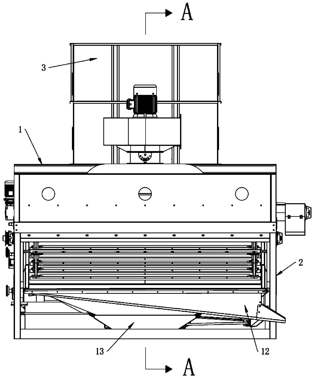
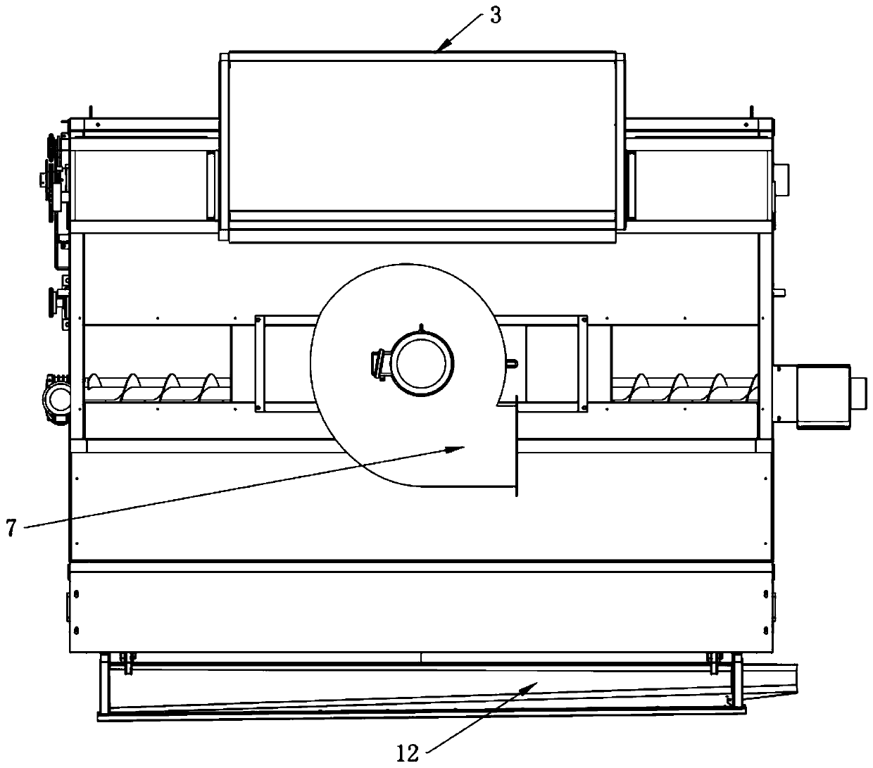
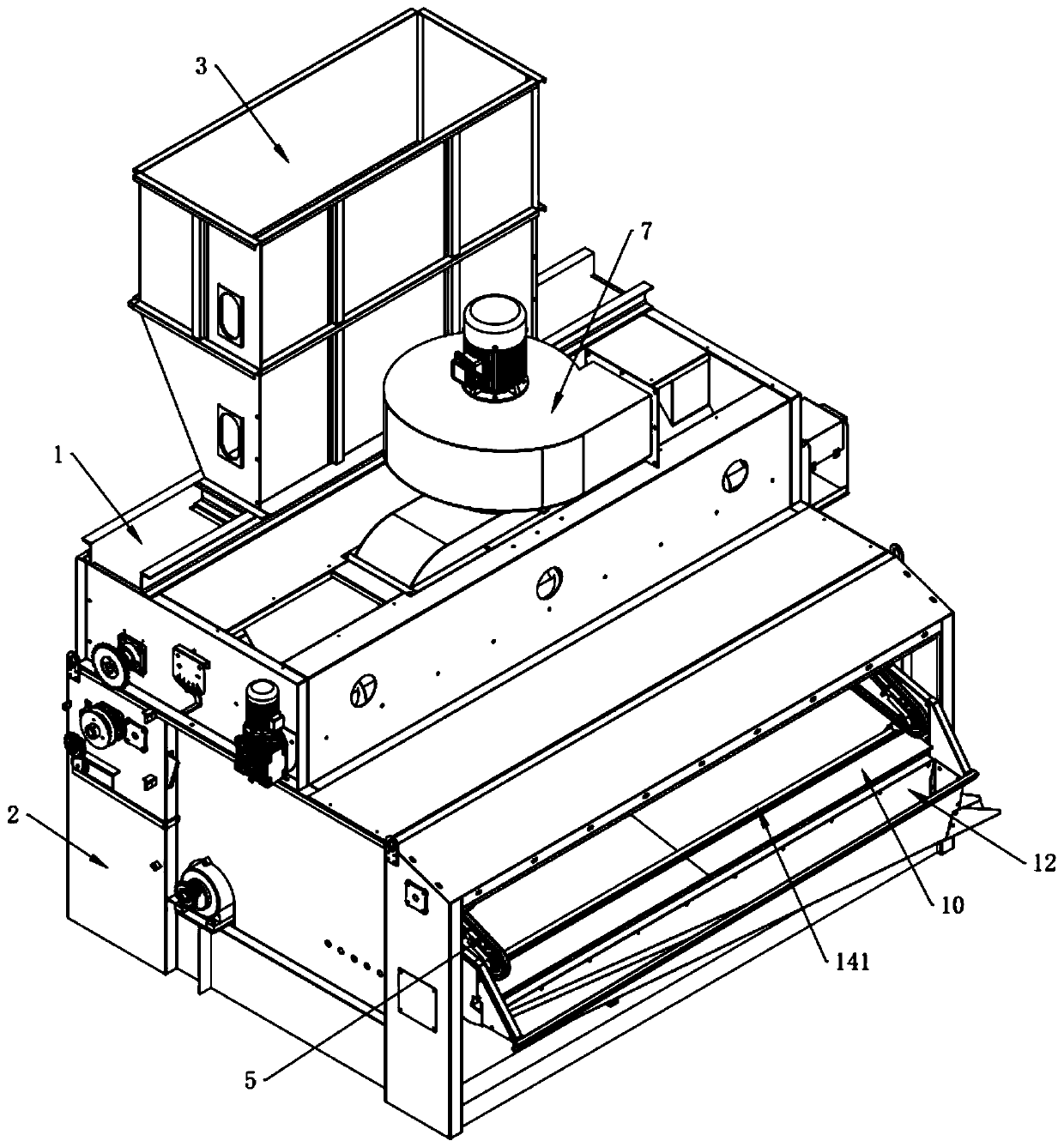
[0028] See Figure 1-8 , The present invention provides a technical solution:

[0029] A grain screening machine with a scraper cleaning structure, comprising a feed box 1, a trash removal box 2 and a storage hopper 3. A trash removal box 2 is arranged above the feed box 1, a trash removal box 2 and a feed box 1 The storage hopper 3 is connected to the top of the trash removal box 2, and the bottom of the storage hopper 3 is connected to ...


PUM


Abstract

The invention discloses a grain screening machine with scraping plates impurities removing structure. The machine comprises a feeding box, an impurities removing box and a material storage hopper, wherein a grain stirring wheel is arranged in the feeding box, a discharging pipe is arranged on one side of the grain stirring wheel, a light impurities outputting opening is formed in one side, far away from the grain stirring wheel, of the discharging pipe, and a fan is fixedly arranged above the light impurities outputting opening; and the chain is sequentially and fixedly connected with a nylonscraping plate device, a brush scraping plate device and a PVC scraping plate device, wherein the nylon scraping plate device comprises an installing mechanism and a nylon scraping plate, the brush scraping plate device comprises an installing mechanism and a brush scraping plate, the PVC scraping plate device comprises an installing mechanism and a PVC scraping plate. According to the machine, the impurities which cannot be removed on the existing machine can be well removed by comprehensively using the scraping plates of three different materials, labor is saved, and meanwhile, the production yield is greatly improved under the condition that the size of an original screening net surface is not changed, the practicability is strong, and the machine is worthy of popularizing.

Description

technical field [0001] The invention relates to the technical field of grain screening, in particular to a grain screening machine with a scraper structure for removing impurities. Background technique [0002] At present, the sieves for removing impurities in grains are cylindrical sieves and vibrating sieves. Due to the low output of cylindrical sieves, the impurity removal effect generally cannot meet the needs of most users. At present, the impurities removal of vibrating screens on the market is divided into light impurities, medium impurities and large impurities. Light impurities are removed by fans, and medium impurities and large impurities are removed by rolling or vibrating through screens. Due to different types of grains such as rice, wheat and corn, etc., Its impurity content and water content are also different, resulting in poor yield and impurity removal effect. [0003] There are obvious defects in the existing vibrating screen: the grains are piled up in ...

Claims


Application Information

Patent Timeline
IPC IPC(8): B07B9/00B07B4/02B07B1/28B07B1/52
Inventor 卢业青戴怀龙
Owner ANHUI VISION OPTOELECTRONICS TECH
Why Eureka
Try Eureka