Three-way pipe forming method, forming device and forming system

A forming method and a forming device technology, which are applied in the field of automatic processing equipment, can solve problems such as complicated procedures and few structural types of three-way pipes, and achieve the effect of improving flexibility

Pending Publication Date: 2019-06-28
浙江长兴和良智能装备有限公司
View PDF14 Cites 0 Cited by
  • Summary
  • Abstract
  • Description
  • Claims
  • Application Information

AI Technical Summary

Problems solved by technology

Although this equipment has improved the degree of automation, it needs to be flattened before internal pressure forming i...

Method used


Image

  • Three-way pipe forming method, forming device and forming system
  • Three-way pipe forming method, forming device and forming system
  • Three-way pipe forming method, forming device and forming system

Examples


Embodiment 1

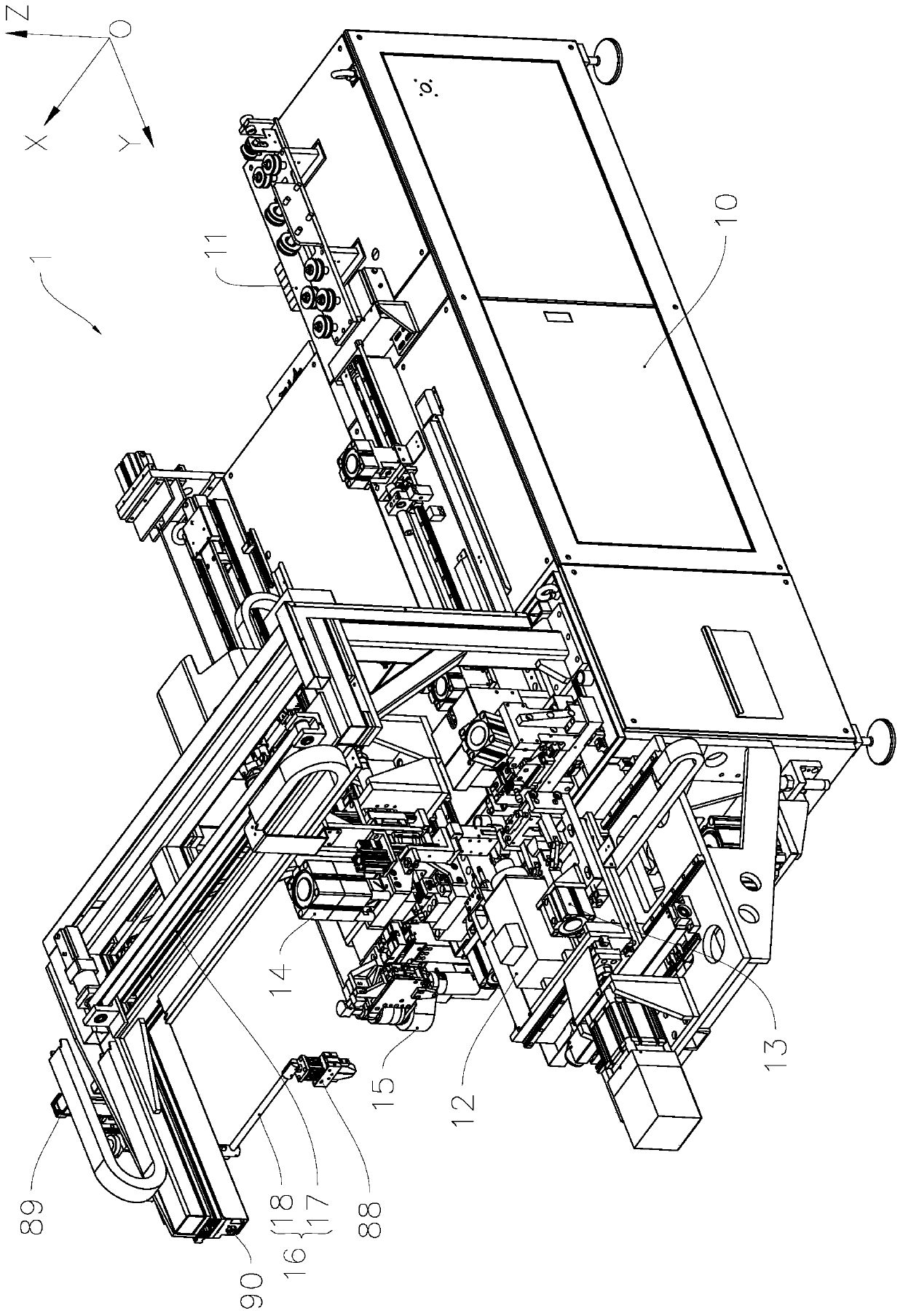
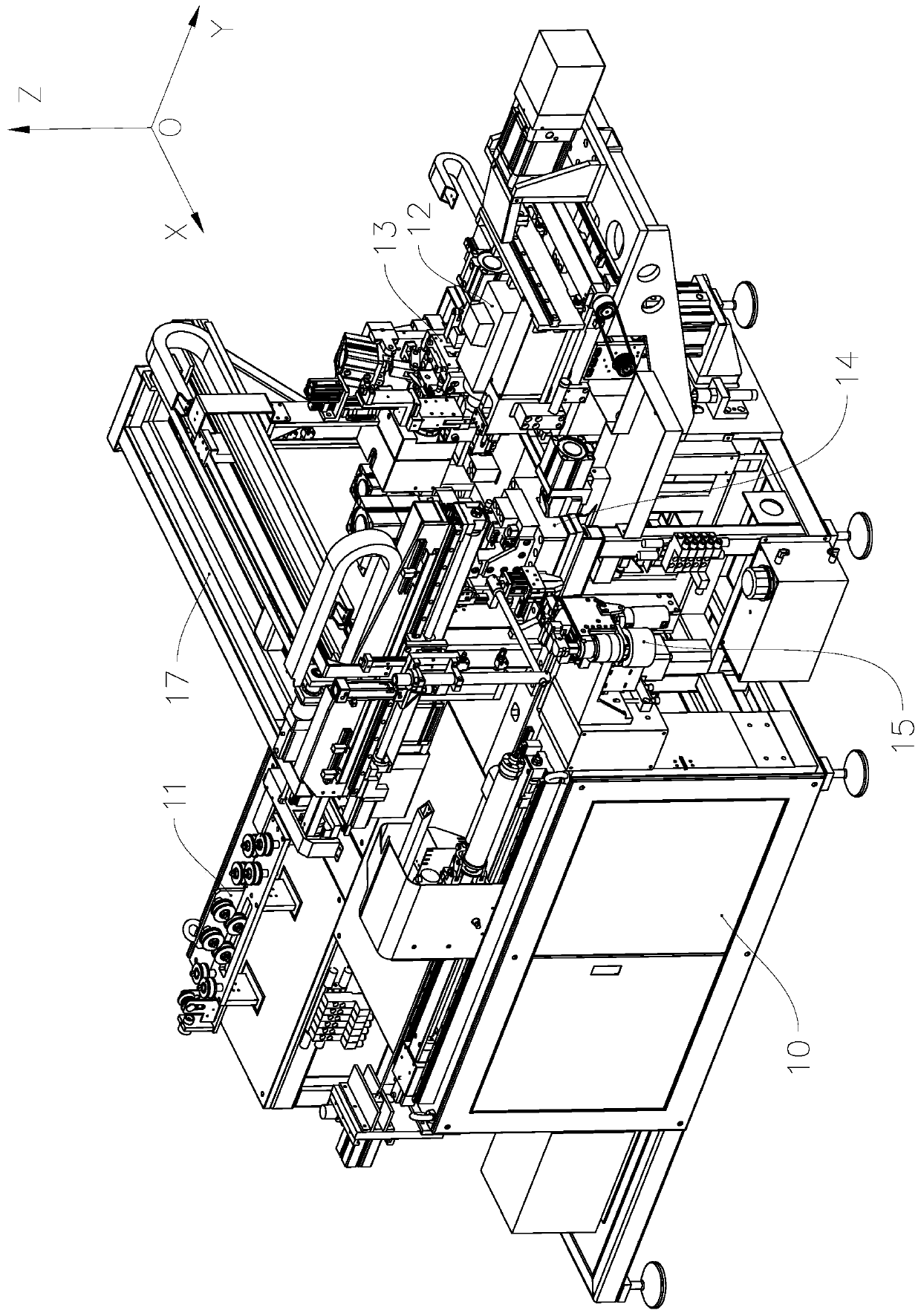
[0043] see Figure 1 to Figure 17 The three-way pipe forming system 1 of the present invention includes a frame 10 and a feeding device 11 installed on the frame 10, a flaring device 12, a forming device 13, a pipe end processing device 14, a pipe bending device 15 and a moving device. The material manipulator system 16, the material transfer manipulator system 16 is used to sequentially transfer pipe materials between each device, the material transfer manipulator system 16 includes a traverse manipulator system 17 and a bend pipe loading and unloading manipulator system 18, so that each device can be processed according to the process sequence , sequentially process the pipe material to obtain such as Figure 18 Tee pipe 01 of the structure shown.

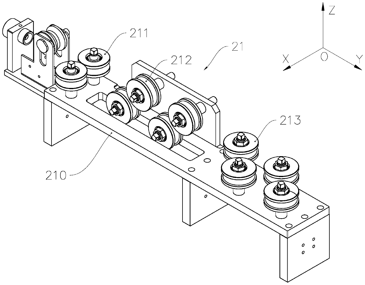
[0044] like Figure 1 to Figure 5 and Figure 8 As shown, the feeding device 11 includes a straightening unit 21 , a feeding unit 22 , a fixed pulling die 23 , a chipless rotary cutting head 24 , a moving pulling die 25 and a p...

Embodiment 2

[0078] As an explanation of Embodiment 2 of the molding system of the present invention, only the differences from Embodiment 1 of the above-mentioned molding system will be described below.

[0079] see Figure 19 , the extruded protrusions 71, 72 of the distance expansion unit are used to squeeze the gap 61020 between the two mandrel seats 61, 62 to expand the gap, thereby driving the distance between the two forming mandrels 63, 64 to expand , that is, in this embodiment, the distance expanding unit is used to squeeze out the gap between the two mandrel seats. At this time, the stress-bearing part on the non-forming rod part is the fixed section of the forming mandrel on the mandrel seat.

[0080] refer to figure 1 In the structure shown, for the traversing manipulator system 17 and the bending pipe loading and unloading manipulator system 18, the degree of freedom of movement along the Y-axis can be added to the traversing manipulator system 17 to form a three-dimensiona...


PUM


Abstract

The invention relates to a three-way pipe forming method, forming device and forming system and belongs to the technical field of automatic machining. The forming method comprises the steps that (1) two forming mandrels are inserted into a to-be-pressed pipe portion, and the distance between the two forming mandrels can be adjusted outwards in an expanding mode; and (2) the to-be-pressed pipe portion is extruded from two side surfaces by means of an inward pressing male die portion, so that the distance between the mandrels is expanded and the pipe wall of the to-be-pressed pipe portion is extruded in the process that an inwards concave pipe wall structure is pressed between the two forming mandrels, and a three-way pipe structure is formed. By means of the forming method, a flattening procedure and an inward pressing forming procedure in the prior art can be achieved in the same procedure, in addition, the forming structure conversion flexibility can be improved, and the forming method can be widely applied to the manufacturing field of aviation, refrigeration, automobiles and the like.

Description

technical field [0001] The invention relates to the field of automatic processing equipment, in particular to a method for forming a three-way pipe, a forming device and a forming system suitable for using the forming method. Background technique [0002] Tee pipes are often used in air-conditioning and refrigeration systems to connect multi-channel pipes. For its processing, it is usually necessary to flaring one end first, and then flat forming the flared end. Commonly used processing methods include manual production and semi-automatic processing. Among them, the manual method uses pure manual flaring and flat forming, which is time-consuming, laborious, low production efficiency, high labor cost, and is not suitable for mass production; while the semi-automatic processing method uses semi-mechanical and semi-automatic processing. Manual operation, the worker first clamps the tee on the machine tool through the fixture, and then expands the mouth with the flaring tool. A...

Claims


Application Information

Patent Timeline
IPC IPC(8): B21D43/04B21D3/02B21D41/02B21D35/00B21D31/04B21D43/00B21D7/00B21D37/10B21D45/08B23P23/04
Inventor 席伟江王元宾张良赵俊强黄磊
Owner 浙江长兴和良智能装备有限公司
Why Eureka
Try Eureka