Disassembling and assembling device of corner clamping plate positioning and tensioning device

A technology of tensioning device and splint, which is applied in the direction of collets, manufacturing tools, manipulators, etc., can solve the problems of time-consuming and laborious disassembly, limited manpower, and heavy tensioning device, so as to avoid malfunction damage, improve productivity, and liberate The effect of human labor

Active Publication Date: 2019-06-28
SHANGHAI JIAO TONG UNIV +1
View PDF5 Cites 3 Cited by
  • Summary
  • Abstract
  • Description
  • Claims
  • Application Information

AI Technical Summary

Problems solved by technology

This method has the following problems: 1. In order to ensure the bonding strength, the rubber belt or the spring tensioner must have sufficient tension, but the manpower is limited, and the tensioner is relatively heavy, so the disassembly operation is very time-consuming and laborious, and it is easy to cause damage. Industrial accidents; 2. Manual work is easy to cause damage to the bonded structure and affect the bonding quality

Method used


Image

  • Disassembling and assembling device of corner clamping plate positioning and tensioning device
  • Disassembling and assembling device of corner clamping plate positioning and tensioning device
  • Disassembling and assembling device of corner clamping plate positioning and tensioning device

Examples


Embodiment 1

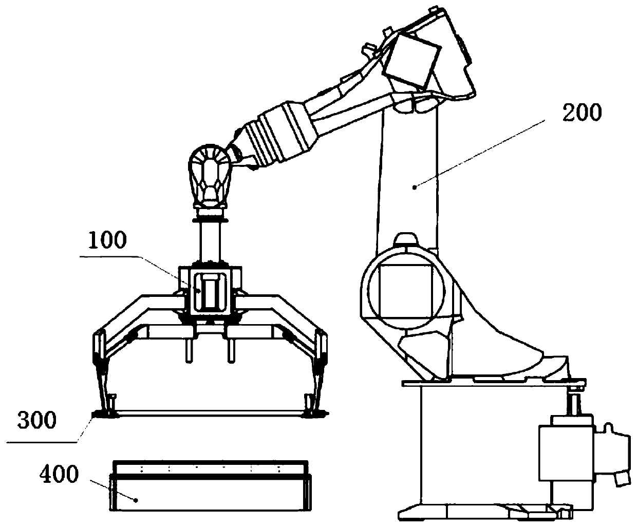
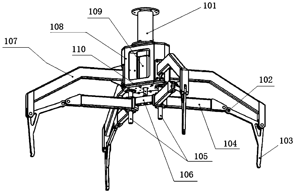
[0045] A disassembly device for positioning and tensioning device 300 used in the production of LNG ship insulating box 400, used for disassembling and assembling the positioning and tensioning device 300, the positioning and tensioning device 300 includes an outer frame 301 sleeved on the side of the insulating box 400, a movable The pull ring 302 and the pressing roller 303 arranged at the end corner of the outer frame 301 and connected to each other, when the positioning and tensioning device 300 is assembled on the insulating box 400, the pressing roller 303 abuts against the corresponding end corner of the insulating box 400, please refer to figure 2 As shown, the dismounting device includes a fixed base 108, a movable base 106, a driver, a fixed arm 107, a movable arm 104 and a gripper 103, wherein the movable base 106 is located below the fixed base 108, and the driver is installed on the fixed base 108 , and is used to connect and drive the movable base 106 to move up ...

Embodiment 2

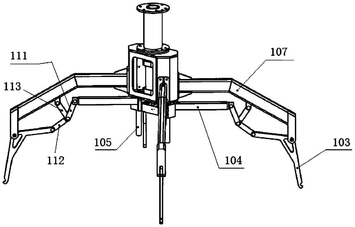
[0079]Compared with Embodiment 1, most of them are the same, except that in this embodiment, the link mechanism between the movable arm 104 and the gripper 103 is movably connected, see image 3 with Figure 4 As shown, the link mechanism includes a first link 111, a second link 112 and a third link 113, wherein one end of the first link 111, the second link 112 and the third link 113 are hinged together, The other end is respectively hinged with the movable arm 104, the handle 103 and the fixed arm 107. In a more specific embodiment, when the driving member drives the movable base 106 to move downward, so that the handle 103 catches the pull ring 302 of the positioning tension device 300 and moves outward, and then the pressure roller 303 is completely released, the movable arm 104 Parallel to the first connecting rod 111 , the second connecting rod 112 and the third connecting rod 113 are connected in a straight line. The movable arm 104 is hinged with the gripper 103 thro...

Embodiment 3

[0081] Compared with Embodiment 1 or Embodiment 2, most of them are the same, except that in this embodiment, a pull ring 302 detection mechanism is further provided at the end of the handle 103, see Figure 5 As shown, the detection mechanism of the pull ring 302 includes a rotating shaft 115, a swing rod 114, an induction plate 116, a spring 119 and a proximity switch 117, wherein the middle part of the swing rod 114 is hinged on the handle 103 through the rotating shaft 115, and the upper end of the swing rod 114 is connected to The lower end of the spring 119, the upper end of the spring 119 is also connected with the gripper 103, the induction plate 116 is arranged on the top of the fork 114, and the upper end of the induction plate 116 can be passed through the switch mounting bracket within the range of its swing with the fork 114 118 is fixedly mounted on the proximity switch 117 sensed above it; when the pull ring 302 detection mechanism is not subjected to external fo...


PUM


Abstract

The invention relates to a disassembling and assembling device of a corner clamping plate positioning and tensioning device. The disassembling and assembling device comprises a fixed base, a movable base, a driving part, a fixed arm, a movable arm and a handle, wherein the movable base is arranged below the fixed base, the driving part is installed on the fixed base and is used for connecting anddriving the movable base to move up and down, the fixed arm is arranged on the side surface of the fixed base and is unfolded outwards, and the movable arm is arranged on the movable base and is unfolded outwards; and the handle is L-shaped, the middle bent position of the handle is hinged to the end, which is outwards unfolded, of the fixed arm, one end of the handle is movably connected to the end part, which is outwards unfolded, of the movable arm, and the other end of the handle is bent downwards. Compared with the prior art, the disassembling and assembling device can replace manual assembling and disassembling of the positioning and tensioning device, the labor is liberated, the production rate is improved, and the bonding quality of a corner clamping plate is improved.

Description

technical field [0001] The invention belongs to the technical field of assembly and disassembly equipment, and relates to a disassembly and assembly device for a corner splint positioning and tensioning device. Background technique [0002] Part of the box type of the LNG marine polyurethane insulation box adopts a sandwich structure of plywood→polyurethane board→plywood bonded layer by layer, and the four corners need to be bonded with corner splints. For special working conditions such as turbulence and low temperature at sea, this kind of box has strict requirements on bonding strength and assembly accuracy. At present, the assembly of the corner splints at home and abroad is manual operation, and the fixation after gluing is manually tensioned by rubber belt or spring tensioning device, and the subsequent aging planning process is carried out. This method has the following problems: 1. In order to ensure the bonding strength, the rubber belt or the spring tensioner must...

Claims


Application Information

Patent Timeline
Patent Type & Authority Applications(China)
IPC IPC(8): B25J15/02B25J15/08B25J19/00
Inventor 蒋知峰孔谅梁诚周春立张立中冯炜杰金鑫张悦
Owner SHANGHAI JIAO TONG UNIV
Why Eureka
Try Eureka