Full-automatic magnetic tile sticking machine

A magnetic tile machine, fully automatic technology, applied in the manufacture of stator/rotor body and other directions, can solve the problems of non-compliance with the quality management system and humanized development ideas, high labor cost input, and low efficiency of magnetic tile sticking.

Active Publication Date: 2015-07-22
GUANGZHOU FIRESTEP SELF CONTROL SPECIAL PURPOSE EQUIP +1
View PDF4 Cites 19 Cited by
  • Summary
  • Abstract
  • Description
  • Claims
  • Application Information

AI Technical Summary

Problems solved by technology

[0003] For the process of gluing magnetic tiles, most manufacturers still use traditional manual gluing, which has problems such as low gluing efficiency, unstable glue quality due to non-standardized production and other factors, and high labor costs. The industrial glue used in artificial gluing will cause harm to the human body, and the production process does not conform to the quality management system and humanized development ideas of modern enterprises. , so that labor-intensive enterprises are forced to accept the process of forced transformation, and the market for using automated equipment to replace manual op

Method used


Image

  • Full-automatic magnetic tile sticking machine
  • Full-automatic magnetic tile sticking machine
  • Full-automatic magnetic tile sticking machine

Examples


Embodiment 1

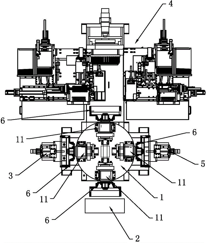
[0071] like Figure 1 to Figure 6 As shown, a fully automatic tile sticking machine includes a control system and a rotatable turntable mechanism 1 with at least four stations arranged in a ring. Each station of the turntable mechanism 1 is provided with a clamping rotor 6. The shaft expansion mechanism 11 also includes a loading and unloading mechanism 2, a glue application mechanism 3, a magnetic tile mounting mechanism 4 and a filling glue glue application mechanism 5 arranged in sequence.

[0072] The loading and unloading mechanism 2 includes the loading and unloading manipulator for feeding and taking out the rotor 6 into and out of the shaft expansion mechanism 11 and the loading and unloading positioning drive device for driving the loading and unloading manipulator; the glue applying mechanism 3 includes applying glue to the rotor. The first gluing machine on the inner wall of 6 and the first glue head positioning drive device for driving the first gluing machine; the...

Embodiment 2

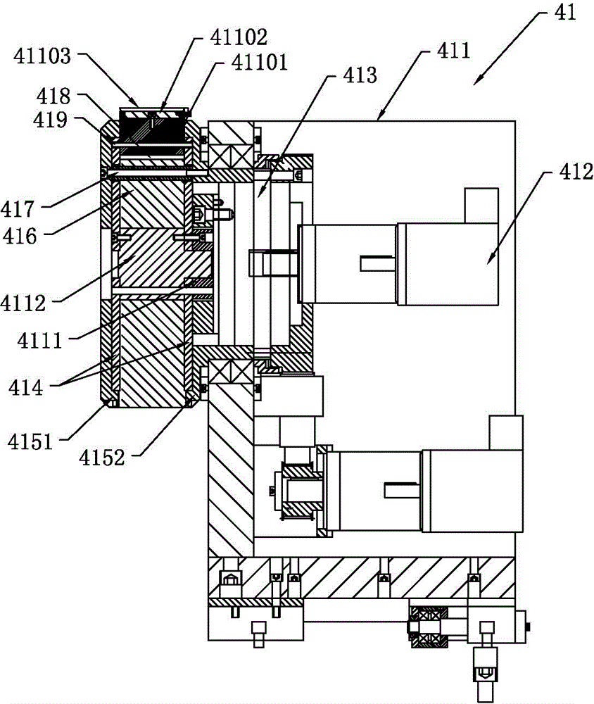
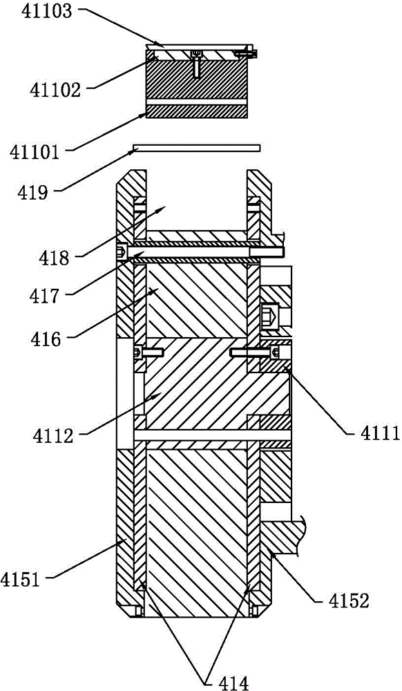
[0080] One of the implementation modes of a fully automatic tile sticking machine of the present invention, such as Figure 1 to Figure 7 As shown, the main technical solutions of this embodiment are basically the same as those of Embodiment 1, and the features not explained in this embodiment are explained in Embodiment 1, and will not be repeated here. The difference between this embodiment and embodiment 1 is: as Figure 7As shown, the magnetic tile library device 41 also includes a protective cover 4113 and a protective cover driving device 4114 that drives the movement of the protective cover 4113. The protective cover 4113 is arranged in a bottomless cylindrical shape, and the protective cover 4113 covers the charging unit 4110 inside. .

[0081] The protective sheath driving device 4114 is drivingly connected with the protective sheath 4113 . Wherein, the protective cover driving device 4114 includes a servo motor 4116, a driving wheel 4115, a synchronous belt and fou...

Embodiment 3

[0084] One of the implementation modes of a fully automatic tile sticking machine of the present invention, such as Figure 1 to Figure 11 As shown, the main technical solution of this embodiment is basically the same as that of embodiment 1 or embodiment 2, and the features not explained in this embodiment are explained in embodiment 1 or embodiment 2, and will not be repeated here . The difference between this embodiment and embodiment 1 or embodiment 2 is: as Figure 8 to Figure 11 As shown, the magnetic tile pushing device 42 includes a pushing controller, a first pushing mechanism, a Hall sensor 425, a turning mechanism, a second pushing mechanism discharge device 4211 and a third pushing mechanism, and the first pushing mechanism includes a first push rod 421 , the first guide rod 423 and the first push rod 421 drive device for driving the first push rod 421 to move along the first guide rod 423, the first push rod 421 drive device is connected with the push controller ...


PUM


Abstract

The invention relates to a full-automatic magnetic tile sticking machine which comprises a control system, a rotatable turnplate mechanism, a feeding mechanism, a discharging mechanism, a gluing mechanism, a magnetic tile sticking and mounting mechanism and a filling glue coating mechanism. The feeding mechanism, the discharging mechanism, the gluing mechanism, the magnetic tile sticking and mounting mechanism and the filling glue coating mechanism are arranged sequentially, the magnetic tile sticking and mounting mechanism comprises a magnetic tile library driving device, an intermediate wheel, two driving plates, multiple pins and multiple loading units capable of adsorbing magnetic tiles, the magnetic tile library driving device can drive the driving plates to rotate, the intermediate wheel is fixedly arranged between the driving plates, multiple guide grooves are formed between the outer wall of the periphery of the intermediate wheel and the side walls of the driving plates, each loading unit is mounted in the corresponding guide groove, each driving plate is provided with multiple pin driving mechanisms corresponding to the loading units, and the pin driving mechanism are used for pushing the pins to move. The magnetic tile sticking and mounting mechanism adopts a magnetic tile library to adsorb the magnetic tiles needed by a rotor to the loading units of the magnetic tile library, and the loading units move outwards at the same time to stick the magnetic tiles to the inner wall of the rotor at the same time when the driving plates rotate, so that the full-automatic magnetic tile sticking machine is high in efficiency and quality.

Description

technical field [0001] The invention relates to the technical field of magnetic tile pasting, in particular to a fully automatic magnetic tile pasting machine. Background technique [0002] With the continuous development of society, the degree of automation of various electrical equipment is getting higher and higher, and the use of motors is becoming more and more extensive, especially permanent magnet DC motors. Permanent magnet DC motors are widely used in various household appliances, power equipment, precision testing equipment, automotive appliances, etc. due to their stable performance and large torque. At present, the stator magnetic tiles of permanent magnet motors are generally fixed by strong adhesive Glue-type fixing, but the process of magnetic tile gluing is more complicated. It not only requires the glue used to be able to withstand large torque and complex and harsh working environment, but also requires precise positioning of the installation size of the ma...

Claims


Application Information

Patent Timeline
IPC IPC(8): H02K15/03
Inventor 姚牧徐永谦方原龙
Owner GUANGZHOU FIRESTEP SELF CONTROL SPECIAL PURPOSE EQUIP
Why Eureka
Try Eureka