Two-dimensional fluid aircraft

An aircraft and fluid technology, applied in the field of aircraft, to achieve low energy consumption, improved performance, and strong practicability

Pending Publication Date: 2019-06-28
涂常青
View PDF5 Cites 0 Cited by
  • Summary
  • Abstract
  • Description
  • Claims
  • Application Information

AI Technical Summary

Problems solved by technology

[0007] The present invention provides a two-dimensional fluid aircraft, aiming to solve the above-mentioned problems existing in the two-dimensional fluid aircraft in the prior art

Method used


Image

  • Two-dimensional fluid aircraft
  • Two-dimensional fluid aircraft
  • Two-dimensional fluid aircraft

Examples


Embodiment

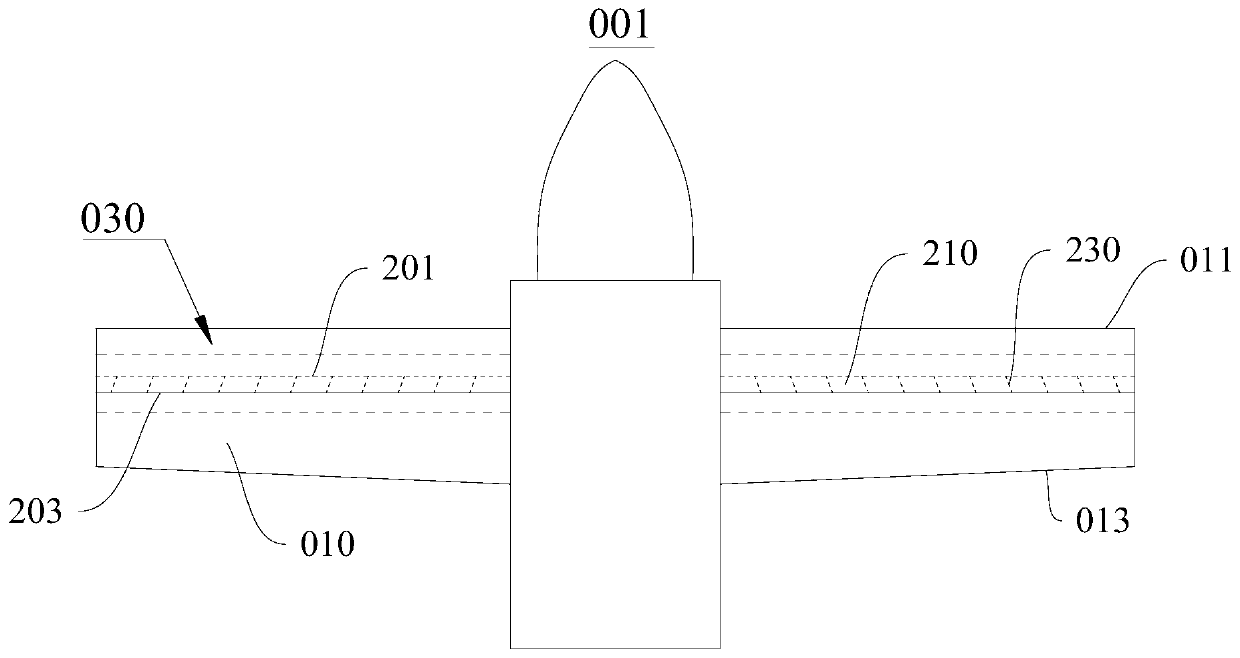
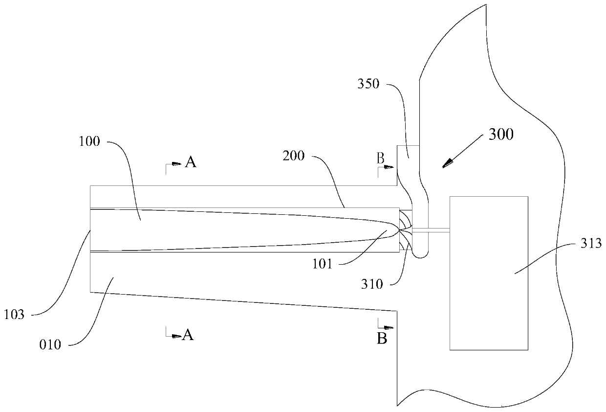
[0041] This embodiment provides a two-dimensional fluid aircraft 001, please refer to figure 1 and figure 2 , this two-dimensional fluid aircraft 001 includes wing body 010 and two-dimensional fluid converter 030; An installation space for installing the rectifying cap 100, a rectifying space is formed between the retaining wall 200 and the outer wall of the rectifying cap 100;

[0042] Retaining wall 200 conforms to the arc of equal differential diameter reduction, and has small diameter layer 201 and large diameter layer 203; The set small diameter end 101 and large diameter end 103;

[0043] The axial center of the blocking wall 200 coincides with the axial center of the rectifying cap 100; the side portion of the blocking wall 200 is formed with a rectification outlet 210 communicating with the rectification space; gap formation;

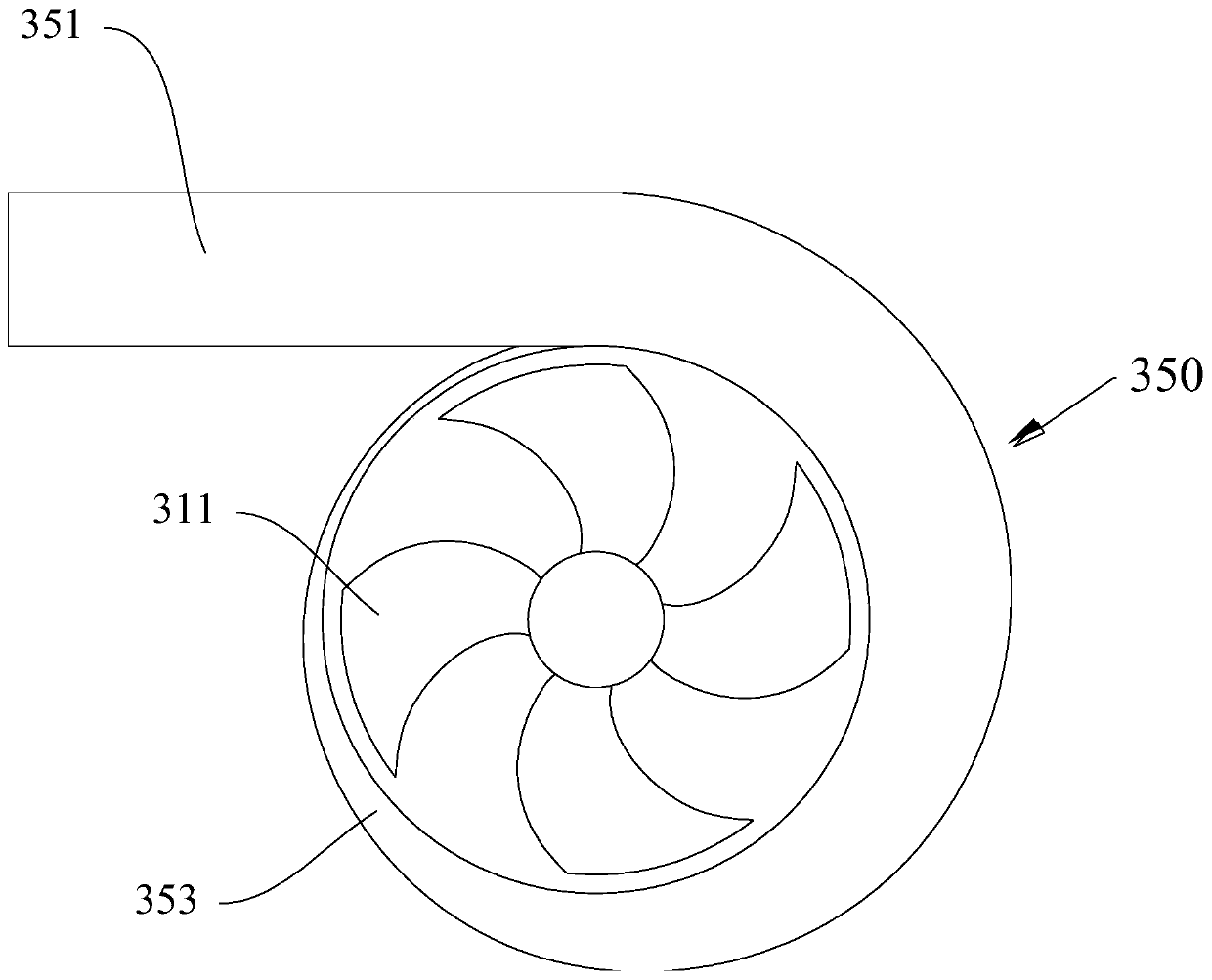
[0044] The drainage assembly 300 includes a fluid outlet, and the fluid outlet faces the small-diameter end 101 of the fairing cap 100; th...


PUM


Abstract

The invention provides a two-dimensional fluid aircraft and belongs to the field of aircrafts. The two-dimensional fluid aircraft comprises wings and two-dimensional fluid converters; each two-dimensional fluid converter comprises a rectification cap, a retaining wall and a drainage assembly for introducing airflow, mounting spaces for installing the rectification caps are formed at the inner sides of the retaining walls, and rectification spaces are formed between the retaining walls and the outer walls of the rectification caps; the retaining walls accord with equal-difference variable-diameter arcs; the outer sides of the radial cross sections of the rectification caps are circular; rectification outlets communicated with the rectification spaces are formed in the sides of the retainingwalls; each drainage assembly comprises a fluid outlet, and the fluid outlet faces small-diameter ends of the rectification caps; each wing is provided with a windward side and a leeward side which are oppositely arranged, an arch face is arranged between each windward side and the corresponding leeward side, and the rectification outlets are formed at the windward sides of the arch faces and face the leeward sides. According to the two-dimensional fluid aircraft, the production cost can be lowered, the lift force of the aircraft is increased, and disturbance is reduced.

Description

technical field [0001] The present invention relates to the field of aircraft, in particular to a two-dimensional fluid aircraft. Background technique [0002] The design purpose of traditional fixed wings is to create a pressure difference between the upper and lower surfaces of the wing to obtain lift. Its method of forming pressure difference is: power plant makes fixed wing carry out relative motion in air. Taking the fixed wing as the reference frame: the air reaches the leading edge of the fixed wing at a relatively high speed, and the air is diverted to the upper and lower surfaces of the wing and accelerates sharply. When the high-speed air passes through the top of the upper surface of the wing, it still has upward inertia, and the curved surface after the top turns to extend downward. nearby undisturbed air, the same below), that is, the pressure on the upper surface of the wing is reduced. Since the lower surface of the wing is a relatively flat surface, when t...

Claims


Application Information

Patent Timeline
Patent Type & Authority Applications(China)
IPC IPC(8): B64C3/36
CPCY02T50/10
Inventor 涂常青
Owner 涂常青
Why Eureka
Try Eureka