
A waste collection device for a punching machine

A technology of waste collection and punching machine, which is applied in the direction of conveyors, conveyor objects, transportation and packaging, etc. It can solve the problems of reducing the working efficiency of the punching machine, and achieves the convenient and fast locking and unlocking process, and the easy and convenient opening and closing process , the effect of improving work efficiency

Active Publication Date: 2020-10-02
台州迪邦科技有限公司
View PDF5 Cites 0 Cited by
  • Summary
  • Abstract
  • Description
  • Claims
  • Application Information

AI Technical Summary

Problems solved by technology

[0003] Since the punching sheet needs to be collected after being punched and formed by the punching machine, but when the traditional waste is collected, it is often collected by a collection tube. When the waste in the collection tube is full, it will be necessary to stop the machine and clean The waste in the machine is removed, which reduces the working efficiency of the film machine, which needs to be improved

Method used


Image

  • A waste collection device for a punching machine
  • A waste collection device for a punching machine
  • A waste collection device for a punching machine

Examples


Embodiment Construction

[0038] The present invention will be described in further detail below in conjunction with the accompanying drawings.

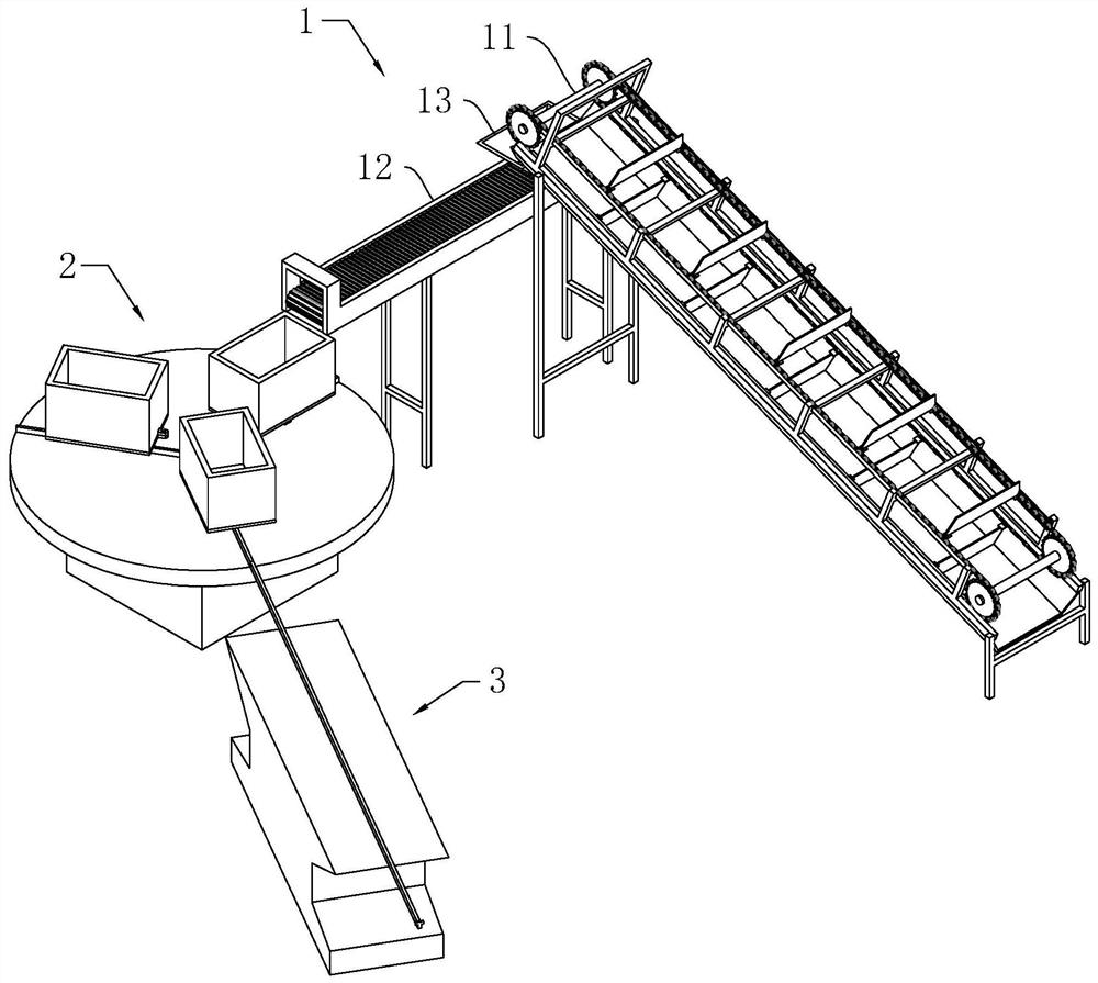
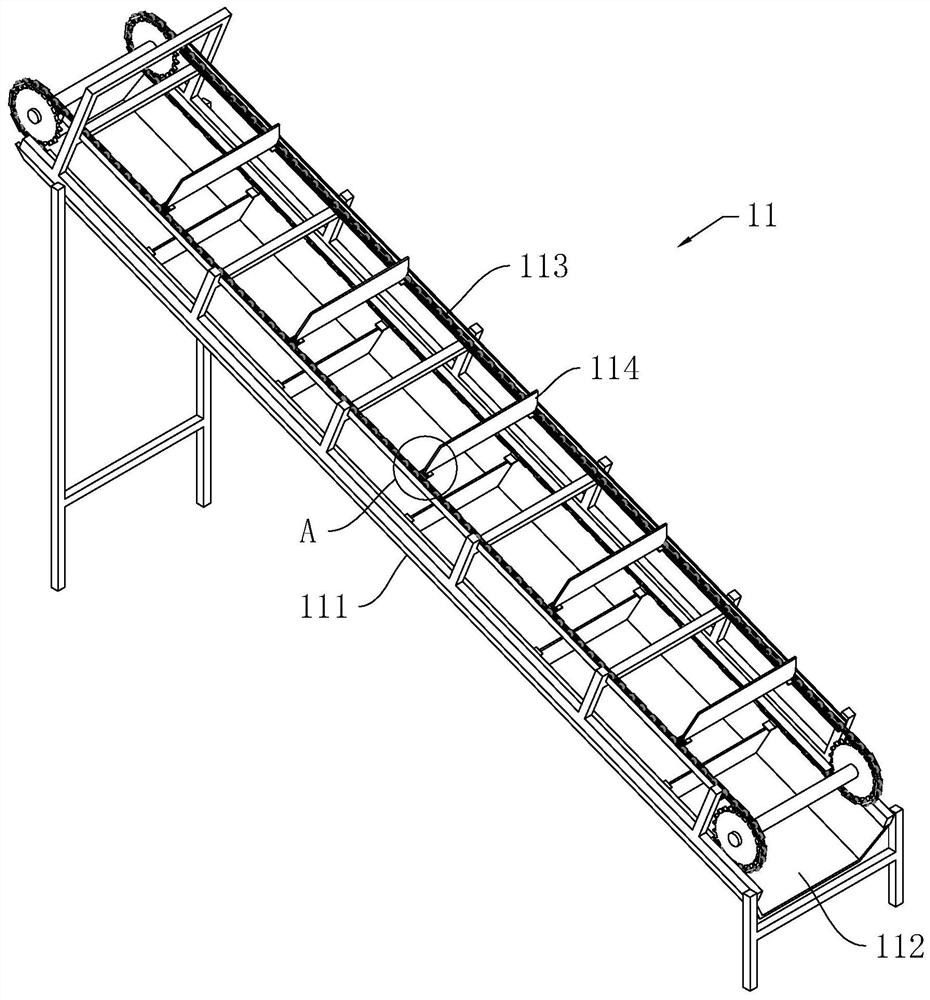
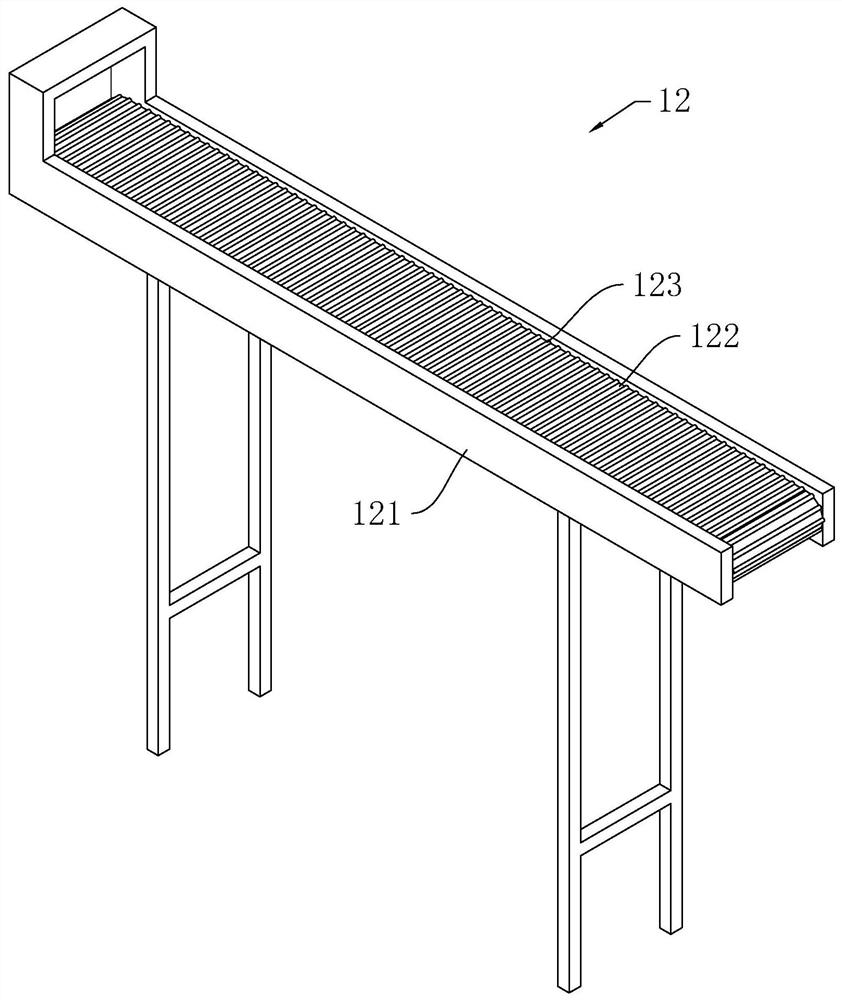
[0039] like figure 1 As shown, a waste collection device for film processing machines includes a transmission mechanism 1, a collection mechanism 2, and a transportation mechanism 3 arranged in sequence. The collection mechanism 2 is located directly below the discharge end of the transmission mechanism 1, and the transportation mechanism 3 is located at the collection mechanism 2. The side wall, and the transportation mechanism 3 can transport the waste to the designated waste collection area.

[0040] When using the collection device to collect waste materials, the waste materials fall onto the conveying mechanism 1 , and at this time, the conveying mechanism 1 is used to convey the waste materials. When the waste material is transported to the end of the transmission mechanism 1 , the waste material falls into the collection mechanism 2 located below it a...


PUM


Abstract

The invention discloses a waste collection device for a sheet punching machine and relates to the field of rotor machining. The waste collection device comprises a conveying mechanism, a collection mechanism and a transportation mechanism. The collection mechanism comprises a base located under the discharge end of the conveying mechanism. A rotary disk is rotatably connected to the base. The rotary disk is provided with a plurality of sliding rails. One ends of the sliding rails are fixed to the center of the rotary disk. The other ends of the sliding rails extend to the outer edge of the rotary disk. Rolling wheels are arranged on the sliding rails. Traveling motors for controlling the rolling wheels to rotate are arranged on the corresponding rolling wheels. Collection tanks are arranged on the rolling wheels. The transportation mechanism comprises a supporting base. A transportation rail is horizontally arranged on the supporting base. One end of the transportation rail is used forcommunicating with the corresponding sliding rails, and the other end of the transportation rail extends to a waste collection area. The waste collection device for a sheet punching machine has the following advantages and effects that the collection tanks operating alternately are used for collecting waste; thus, the sheet punching machine does not need to be stopped, and the waste can be collected continuously; and the working efficiency of the sheet punching machine is substantially improved, and the sheet punching machine can conduct continuous operation without shutdown.

Description

technical field [0001] The invention relates to the field of stator and rotor processing, in particular to a waste material collection device for a punching machine. Background technique [0002] The motor refers to an electromagnetic device that realizes electric energy conversion or transmission according to the law of electromagnetic induction. The motor is mainly composed of a stator and a rotor. The stator and the rotor are respectively composed of a number of stator punches and a number of rotor punches. The punches need to be stamped Tablet machine stamping and forming. [0003] Since the punching sheet needs to be collected after being punched and formed by the punching machine, but when the traditional waste is collected, it is often collected by a collection tube. When the waste in the collection tube is full, it will be necessary to stop the machine and clean The waste in the machine is removed, thereby reducing the working efficiency of the film processor, which...

Claims


Application Information

Patent Timeline
Patent Type & Authority Patents(China)
IPC IPC(8): B65G47/52B65G47/34B65G19/06B65G19/22B65G15/30B65G47/80
Inventor 赵美顺
Owner 台州迪邦科技有限公司
Learn More