
Heat-convection heat exchange device based on vortex ring low-speed circulation air supply

An air supply device and convective heat exchange technology, applied in fluid heaters, household heating, heating methods, etc., can solve the needs of heating that cannot be met, the cost of central heating in the south is high, and the speed of transmission, movement, speed, and export growth are limited by multiples and other issues, achieve significant energy saving and emission reduction and social and economic benefits, improve air supply speed and heating efficiency, and have broad market application prospects

Active Publication Date: 2019-06-28
WUHAN UNIV OF TECH
View PDF10 Cites 8 Cited by
  • Summary
  • Abstract
  • Description
  • Claims
  • Application Information

AI Technical Summary

Problems solved by technology

[0003] The initial cost of central heating in southern my country is very high, and the large-scale construction costs are high, making it difficult to centrally heat
[0004] Domestic single heating type heaters have disadvantages such as low overall heating efficiency of the room and uneven heating
Air-supply heaters mainly rely on ordinary wind to transmit heat, which requires high wind speed for long-distance transmission, and the user experience is not good. Existing heaters have disadvantages such as high power and fire hazards.
[0005] The existing vortex ring generation method mainly relies on splints or pistons to push a section of fluid column, and the vortex ring is generated by the curling of the fluid column at the outlet.
Increasing the outlet growth rate will reduce the ventilation volume of the vortex ring, and the movement speed of the splint piston is limited by the motor and cannot be greatly increased
Therefore, the ventilation volume and propagation speed of the vortex ring are often not balanced, and the heating demand cannot be met.

Method used


Image

  • Heat-convection heat exchange device based on vortex ring low-speed circulation air supply
  • Heat-convection heat exchange device based on vortex ring low-speed circulation air supply
  • Heat-convection heat exchange device based on vortex ring low-speed circulation air supply

Examples


Embodiment Construction

[0026] The present invention will be described in detail below in conjunction with the accompanying drawings and embodiments.

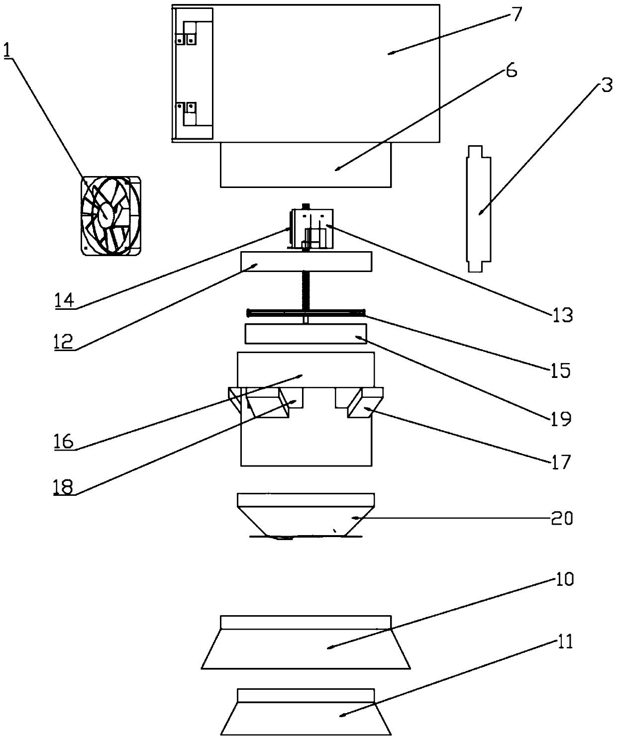
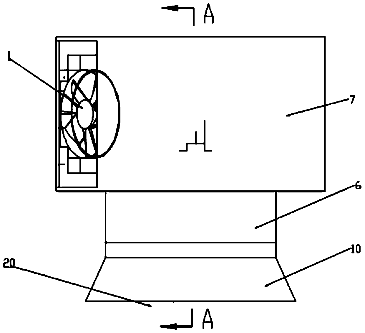
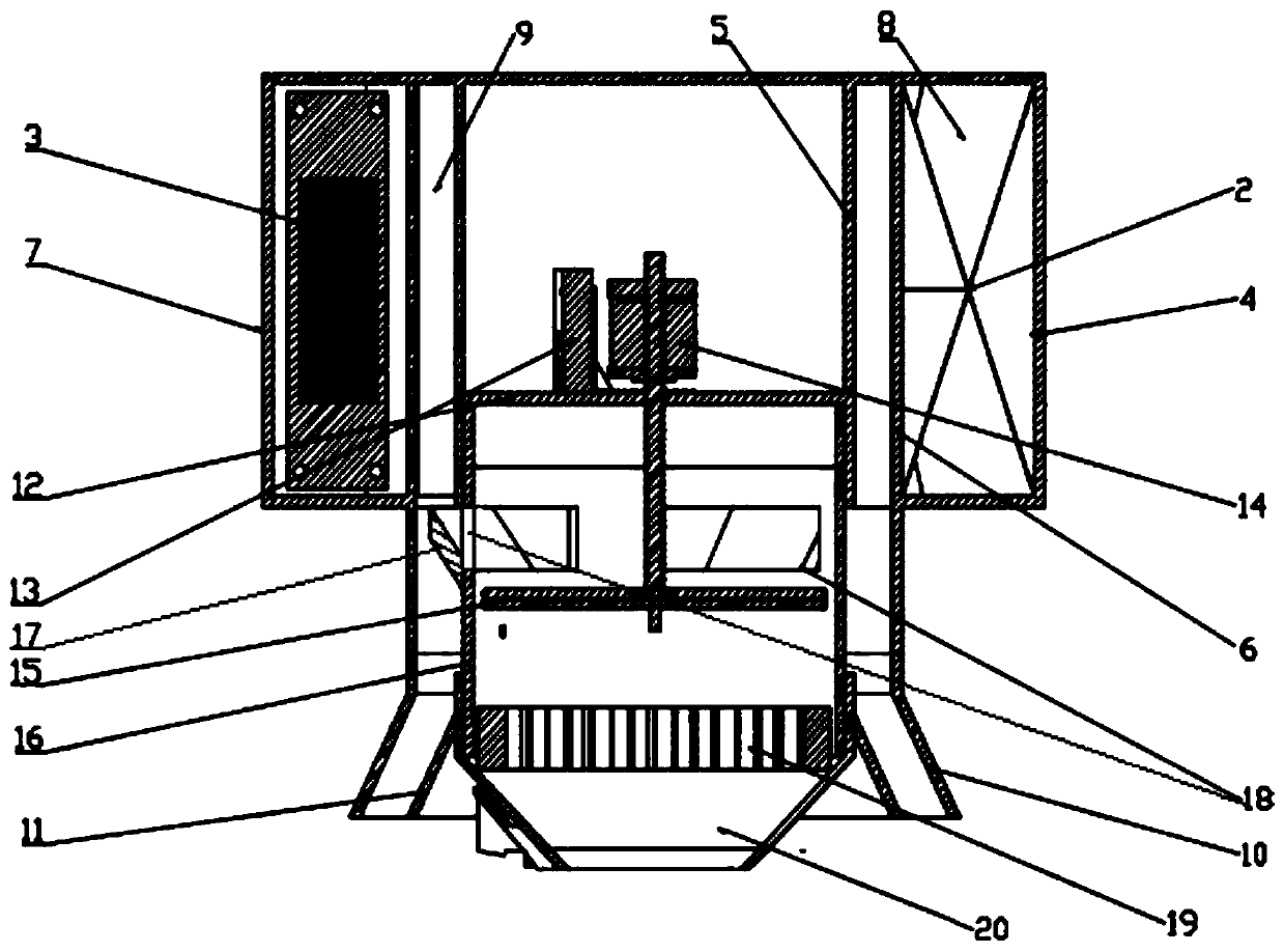
[0027] refer to Figure 1 ~ Figure 3 As shown, the convective heat exchange device based on the vortex ring low-speed circulation air supply in an embodiment provided by the present invention includes a combined heating device, an annular air supply device and a vortex ring air supply device, and the combined heating device is arranged on the vortex ring air supply device. On the upper end of the device, the annular air supply device is sheathed outside the vortex ring air supply device, and the upper ends of the vortex ring air supply device and the upper end of the annular air supply device communicate with the combined heating device respectively.

[0028] Further, the combined heating device includes an annular heat exchange flow channel 8, a speed-increasing flow channel 9, an axial flow fan 1, a carbon fiber paper heating sheet 2 and a PTC ceram...


PUM


Abstract

The invention discloses a heat-convection heat exchange device based on vortex ring low-speed circulation air supply. The heat-convection heat exchange device based on vortex ring low-speed circulation air supply comprises a combined heating device, an annular air supply device and a vortex ring air supply device, wherein the combined heating device is arranged at the upper end of the vortex ringair supply device; the annular air supply device is arranged outside the vortex ring air supply device in a sleeving way; and the upper end of the vortex ring air supply device and the upper end of the annular air supply device communicate with the combined heating device. According to the heat-convection heat exchange device based on vortex ring low-speed circulation air supply provided by the invention, the air supply speed and the heating efficiency are improved, the use experience of a heater is improved, the energy waste caused by uneven indoor temperature distribution is reduced, and theheat-convection heat exchange device based on vortex ring low-speed circulation air supply has remarkable energy conservation, emission reduction and socioeconomic performances, is broad in market application prospect, forms a heat circulation system, and realizes a heating system with low energy consumption and high efficiency.

Description

technical field [0001] The invention relates to the technical field of heating equipment, in particular to a convective heat exchange device based on a vortex ring for low-speed circulating air supply. Background technique [0002] The heating source consumption of towns in northern my country accounts for 36% of the total building energy consumption in the country, and is the largest component of building energy consumption. The average energy consumption is 2-4 times that of developed countries with similar climates. When there is no one inhabited for a medium or long term, the heating is not stopped. When the heating is overheated, it is better to open the window than to close the valve. The waste of heat energy caused by these factors is as high as 20% of the total heat energy, worth tens of billions of yuan. [0003] The initial cost of central heating in southern my country is very high, and the large-scale construction costs are high, making it difficult to centraliz...

Claims


Application Information

Patent Timeline
IPC IPC(8): F24D13/04F24H3/04
Inventor 徐琳李世豪弋戈郑润泽曾龙富赖秋洋刘雨兮刘坤胡詹迪付亿元
Owner WUHAN UNIV OF TECH
Learn More