A multi-combination accelerated air purification laminar flow system and method thereof

An air purification and laminar flow technology, applied in the field of air purification, can solve problems such as affecting instruments or medicines, unable to be put into use quickly, and reduced dust concentration, so as to achieve rapid use and reduce the probability of entering the laminar flow hood. Effect

Active Publication Date: 2020-12-01
浙江博为智能环境科技有限公司
View PDF10 Cites 0 Cited by
  • Summary
  • Abstract
  • Description
  • Claims
  • Application Information

AI Technical Summary

Problems solved by technology

[0002] The laminar flow hood draws the air in the clean room through the intake fan and passes through the operating area vertically through the HEPA filter to provide unidirectional air flow to the area below it. Currently, the laminar flow hood on the market directly extracts the air above it and then dissipates it. Input into the operating area, the exhaust gas is discharged from the bottom of the hood. If the laminar flow hood is only used in part of the clean room, the laminar flow hood will first purify the air above it and the surrounding area, and the exhaust gas will be fused with the original gas and then reduced. The overall dust concentration, but in the subsequent purification process of the laminar flow hood, the dust concentration of the extracted gas is continuously decreasing, and the reduction rate is also decreasing, which makes the dust concentration in other positions in the clean room decrease by several Double the dust concentration around the laminar flow hood, and the laminar flow hood can no longer directly purify the air in other areas. Therefore, the preparation time in the early stage is greatly extended. This process takes a long time and needs to run for 20 minutes at the inlet fan The left and right sides can make the operating area below meet the purification standard and cannot be put into use quickly
[0003] In addition, if the initial dust concentration in the clean room is high, after the exhaust gas flow is discharged vertically from the bottom of the hood, the dust on the ground may be aroused, and the aroused dust may enter the laminar flow hood, which may affect the operation of the equipment It may also affect the instruments or medicines placed in the operating area

Method used


Image

  • A multi-combination accelerated air purification laminar flow system and method thereof
  • A multi-combination accelerated air purification laminar flow system and method thereof
  • A multi-combination accelerated air purification laminar flow system and method thereof

Examples


Embodiment 1

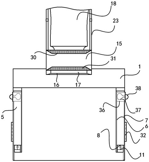
[0064] Such as Figure 1-9 As shown, this embodiment provides a multi-combination accelerated air purification laminar flow system, including a cover body 1, a detection mechanism, an air intake mechanism, a purification mechanism and a control mechanism.

[0065] The control mechanism includes: a processing module 2, which is used to generate work instructions for each component in the system and send the work instructions to the drive module 3; a drive module 3, which is connected to the processing module 2, and is used to receive the work instructions sent by the processing module 2 and drive Each component in the system operates according to a preset program; the storage module 4 is connected to the processing module 2 and is used to store the position information of each connection node in the clean room.

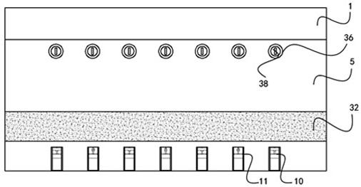
[0066] The cover body 1 includes a transparent blind 5, the blind 5 is arranged in a double-layer structure and is composed of an inner curtain 6 and an outer curtain ...

Embodiment 2

[0084] Such as Figure 1-9 As shown, the present embodiment provides a working method of multiple combined acceleration type air purification laminar flow system, including the following working steps:

[0085] S101: The counter 14 detects the air dust concentration at each connection node in the clean room and sends it to the processing module 2 .

[0086] S102: The processing module 2 extracts the serial number of the counter 14 with the largest sending concentration value and the position of the first air inlet 28 corresponding to the serial number.

[0087] S103: The processing module 2 extracts the electric slider 27 closest to the second electro-hydraulic chuck 25, and generates an intermediate point between the electric slider 27 and the second electro-hydraulic chuck 25 on the track 26.

[0088] S104: The processing module 2 outputs a first sliding signal to the driving module 3, and the driving module 3 drives the electric slider 27 to slide to the middle point posit...

Embodiment 3

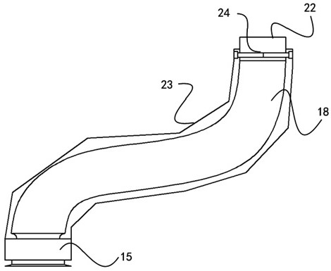
[0109] Such as figure 1 , 3 , 4, 5, 8, and 9, in this embodiment, the processing module 2 calculates the average value of the dust concentration at all connection nodes in real time, and when the dust concentration at the connection node is less than the average value, the processing module 2. Extract the number of the counter 14 with the largest sending concentration value at the current moment, and the position of the second air inlet 28 corresponding to the number; the processing module 2 outputs a disconnection signal to the drive module 3, and the drive module 3 drives the electric pipe frame 23 along the axis shorten until the first connection port 22 is separated from the second connection port 29 .

[0110] The processing module 2 outputs the fourth sliding signal to the driving module 3, and the driving module 3 drives the electric slider 27 to slide to the position of the second air inlet 28; the processing module 2 outputs the third connection signal to the driving...


PUM


Abstract

The invention discloses a multi-combined acceleration type air purification laminar flow system and a method thereof. A cover body comprises a curtain formed by an inner curtain and an outer curtain,a carrying frame and electric sliding rails are arranged between the inner curtain and the outer curtain, and a first guiding fan and a second guiding fan are arranged in the carrying frame; a detection mechanism comprises particle counters arranged at all connection nodes in a clean room; an air inlet mechanism comprises an air inlet fan and an air inlet pipe, wherein a filter layer and a dust discharge valve are arranged on the side wall of the air inlet pipe, a first connecting port is formed in the tail end of the air inlet pipe, an electric pipe frame is sleeved with the air inlet pipe, afirst electro-hydraulic chuck is arranged in the tail end of the electric pipe frame, and a second electro-hydraulic chuck is arranged outside the tail end of the electric pipe frame; and a combineddevice comprises rails arranged on a wall and a ceiling, an electric sliding block embedded in each rail and an air inlet arranged between the rails, and a second connecting port is arranged below theair inlet. According to the multi-combined acceleration type air purification laminar flow system, the overall purification speed in the clean room can be improved, and dust on the ground below the operation area can be prevented from being stimulated.

Description

technical field [0001] The invention relates to the field of air purification, in particular to a multi-combination accelerated air purification laminar flow system and a method thereof. Background technique [0002] The laminar flow hood draws the air in the clean room through the intake fan and passes through the operating area vertically through the HEPA filter to provide unidirectional air flow to the area below it. Currently, the laminar flow hood on the market directly extracts the air above it and then dissipates it. Input into the operating area, the exhaust gas is discharged from the bottom of the hood. If the laminar flow hood is only used in part of the clean room, the laminar flow hood will first purify the air above it and the surrounding area, and the exhaust gas will be fused with the original gas and then reduced. The overall dust concentration, but in the subsequent purification process of the laminar flow hood, the dust concentration of the extracted gas is...

Claims


Application Information

Patent Timeline
Patent Type & Authority Patents(China)
IPC IPC(8): F24F3/16F24F11/64F24F13/02F24F13/28F24F110/50
Inventor 余海晏杨洁
Owner 浙江博为智能环境科技有限公司
Why Eureka
Try Eureka