
Two-dimensional fiber grating inclination sensor

A technology of inclination sensor and optical fiber grating, which is applied in the direction of instrumentation, optical device, machine/structural component testing, etc. It can solve the problems of poor anti-electromagnetic interference performance, large cable line loss, short transmission distance, etc., and achieve the ability to adapt to the environment Strong, fast response, fast monitoring effect

Pending Publication Date: 2019-06-28
SHENYANG JIANZHU UNIVERSITY
View PDF0 Cites 8 Cited by
  • Summary
  • Abstract
  • Description
  • Claims
  • Application Information

AI Technical Summary

Problems solved by technology

The traditional inclination sensor is based on the electromagnetic effect, capacitive effect, etc., and can achieve high accuracy and resolution. However, this type of weak current sensor has the disadvantages of poor anti-electromagnetic interference performance, large cable line loss, and short transmission distance. It is difficult to apply in strong electromagnetic field environment and anti-static environment such as coal mine and oil depot

Method used


Image

  • Two-dimensional fiber grating inclination sensor
  • Two-dimensional fiber grating inclination sensor
  • Two-dimensional fiber grating inclination sensor

Examples


Embodiment Construction

[0026] The present invention will be further described in detail below in conjunction with specific examples, but the protection scope of the present invention is not limited by the specific examples, and the claims shall prevail. In addition, on the premise of not violating the technical solution of the present invention, any modification or change made to the present invention that can be easily realized by those skilled in the art will fall within the scope of the claims of the present invention.

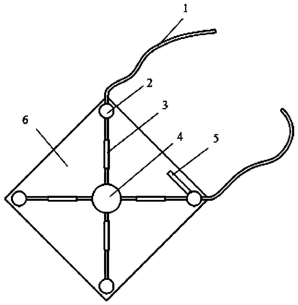
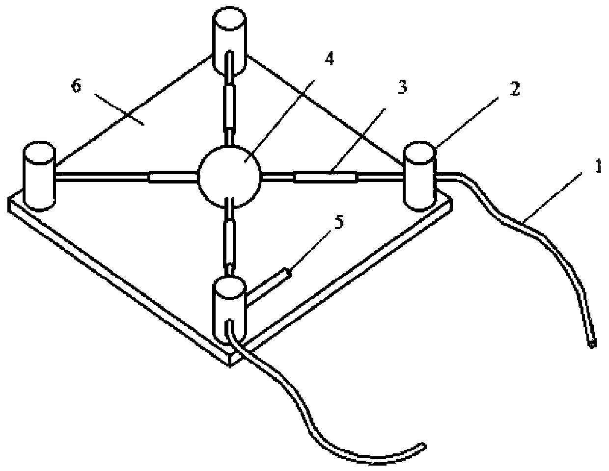
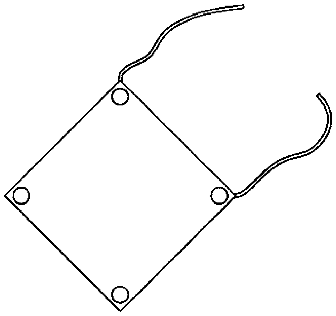
[0027] figure 1 , 2, 3 shows a two-dimensional fiber grating inclination sensor of the present invention, including: a weighted ball, monitoring fiber grating, compensation fiber grating, stainless steel stub, protective housing, fiber loose tube. The main structure is composed of a protective shell, a stainless steel short column and an induction structure. The protective shell 6 is a square box, and two corners are provided with small holes for the loose tube 1 of the optical ...


PUM


Abstract

The invention relates to a two-dimensional fiber grating inclination sensor. The sensor comprises a counterweight ball, monitoring fiber gratings, a compensation fiber grating, short stainless steel columns, a protection casing and loose fiber tubes, wherein the main structure comprises the protection casing, the short stainless steel columns and an induction structure; the protection casing is asquare box with small holes at two corners for allowing the loose fiber tubes to pass through; the short stainless steel columns are located at the four corners of the square protection casing, have acircular cross section and are used for supporting the protection casing; the induction structure comprises the monitoring fiber gratings, the counterweight ball and the compensation fiber grating. The two-dimensional fiber grating inclination sensor is mainly theoretically based on a force balance principle, the monitoring mechanism is to generate two directional component forces in a plane whenthe counterweight ball is subjected to force balance, and accordingly, Bragg reflection wavelength of the fiber gratings changes along with the change of the out-of-plane angle of the sensor. Besides, the cross-sensitivity problem of fiber grating temperature and strain is solved by the compensation fiber grating. The two-dimensional fiber grating inclination sensor has definite structural stress, high response speed, high measurement precision and good stability, has a temperature self-compensation function, is easy to process and manufacture, is resistant to electromagnetic interference andhas better engineering application prospect.

Description

technical field [0001] The invention is based on optical fiber grating sensing technology, is a high-precision instrument for monitoring the inclination angle of soil, rocks and buildings, and belongs to the technical field of optical fiber sensing. Background technique [0002] Large-scale civil engineering projects such as communication tower projects, bridge projects, housing projects and large water tower projects are prone to tilting due to uneven settlement of the foundation, which not only affects the normal use of the structure, but also causes additional stress and even leads to structural damage, resulting in loss of life and property . Therefore, it is necessary to monitor the structural tilt state throughout the construction and operation periods. The traditional inclination sensor is based on the electromagnetic effect, capacitive effect, etc., and can achieve high accuracy and resolution. However, this type of weak current sensor has the disadvantages of poor ...

Claims


Application Information

Patent Timeline
IPC IPC(8): G01B11/26G01B11/16G01M5/00
Inventor 孙丽梁天琦李闯苏中新赵子豪
Owner SHENYANG JIANZHU UNIVERSITY
Learn More