
Optical fiber grating sensor for long-term real-time monitoring of the corrosion on steel bars

A fiber grating and steel bar corrosion technology, which is applied in weather resistance/light resistance/corrosion resistance, instruments, measuring devices, etc., can solve the problems of large individual differences in steel bars, etc., and achieve the effect of easy processing and manufacturing, simple production and wide application range

Inactive Publication Date: 2017-12-22
SHENYANG JIANZHU UNIVERSITY
View PDF8 Cites 5 Cited by
  • Summary
  • Abstract
  • Description
  • Claims
  • Application Information

AI Technical Summary

Problems solved by technology

The fiber grating monitoring steel corrosion method that has been reported in the report, the optical fiber corrosion sensor with micro-bending effect can realize the critical state monitoring of steel corrosion; the Fe-C alloy film corrosion sensor can monitor the initial corrosion; Monitor the specified steel bars, and individual differences in steel bars lead to large errors

Method used


Image

  • Optical fiber grating sensor for long-term real-time monitoring of the corrosion on steel bars
  • Optical fiber grating sensor for long-term real-time monitoring of the corrosion on steel bars
  • Optical fiber grating sensor for long-term real-time monitoring of the corrosion on steel bars

Examples


Embodiment Construction

[0021] The present invention will be further described in detail below in conjunction with specific embodiments, but the protection scope of the present invention is not limited by specific embodiments, and the claims shall prevail. In addition, under the premise of not violating the technical solution of the present invention, any modification or change made to the present invention that can be easily realized by a person of ordinary skill in the art shall fall within the scope of the claims of the present invention.

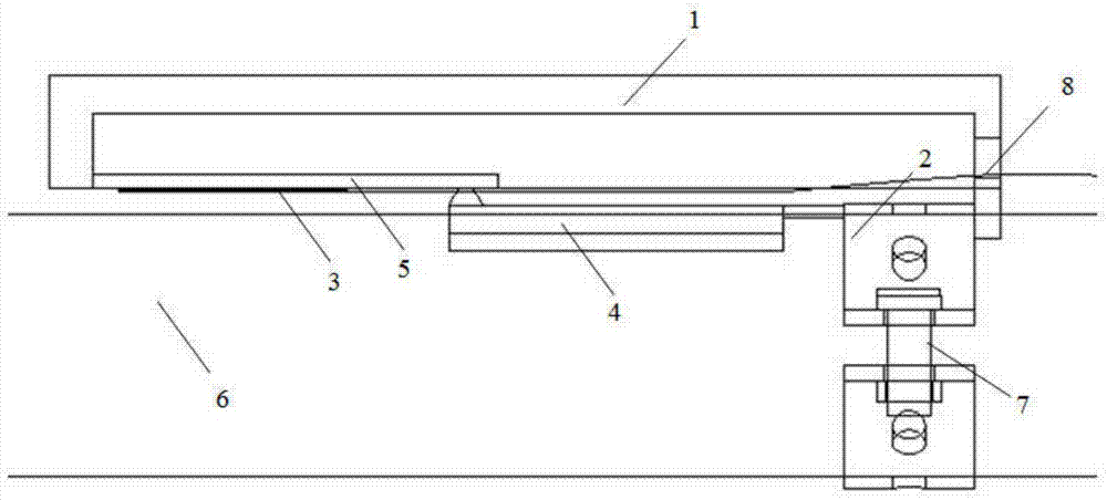
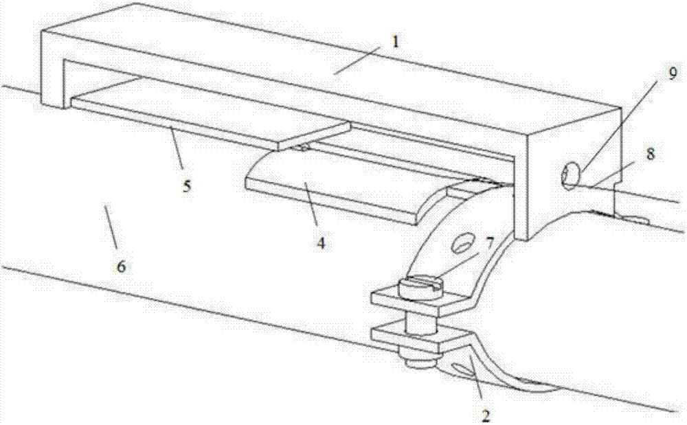
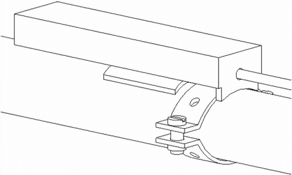
[0022] figure 1 , Shown in 2, 3; a fiber grating sensor for long-term real-time monitoring of steel corrosion, including: protective shell 1, fixed pipe buckle 2, fiber grating 3, conductive cantilever 4, monitoring cantilever 5

[0023] The protective shell 1 is a bottomless rectangular box structure, one side wall is provided with a round hole, and the protective shell 1 is fixed to the steel bar 6 through a fixed pipe buckle 2;

[0024] The protective shell 1 and t...


PUM


Abstract

The present invention discloses an optical fiber grating sensor for long-term real-time monitoring of the corrosion on steel bars. The optical fiber grating sensor comprises a protection shell, a fixation pipe buckle, an optical fiber grating, a conduction cantilever and a monitoring cantilever, wherein a protection shell is a bottomless rectangular box type structure, one side wall of the protection shell is provided with a round hole, the protection shell is fixedly connected to a steel bar through the fixation pipe buckle, the protection shell and the fixation pipe buckle form cementation connection after surface treatment, the protection shell is connected to the monitoring cantilever in a partially embedded manner, the fixation pipe buckle is connected to the conduction cantilever in a partially embedded manner, the monitoring cantilever forms pressing connection at the upper portion of the conduction cantilever, the optical fiber grating is arranged below the monitoring cantilever, and the tail fiber of the optical fiber grating passes through the upper portion of the conduction cantilever, penetrates through the round hole, and then is sleeved with an optical fiber loose sheath. According to the present invention, the optical fiber grating sensor can meet the long-term real-time monitoring of building members, and has advantages of convenient arrangement, simple structure, small size, high measurement precision, good stability, easy manufacture and processing, high sensitivity, anti-electromagnetic interference, adjustable measurement precision, good economic benefits, and good social benefits.

Description

Technical field [0001] The invention relates to optical fiber grating technology and belongs to the technical field of optical fiber sensing, in particular to a sensor used for long-term real-time monitoring of the corrosion state of steel bars in concrete under general atmospheric environment. Background technique [0002] Corrosive environments such as sea water and deicing salt can easily cause corrosion of reinforced concrete structures. Steel corrosion has become the primary factor for insufficient durability of reinforced concrete structures and has attracted widespread attention worldwide. Through the monitoring of the amount of corrosion, the durability of the building components is evaluated, and the dangerous parts are warned in advance to avoid accidents. There are many detection / monitoring methods for steel corrosion, which can be divided into physical detection methods and electrochemical detection methods. Physical detection methods and electrochemical detection me...

Claims


Application Information

Patent Timeline
Patent Type & Authority Applications(China)
IPC IPC(8): G01N17/00G01B11/16
CPCG01B11/16G01N17/006
Inventor 孙丽徐自强朱春阳金峤
Owner SHENYANG JIANZHU UNIVERSITY
Learn More