

Array magnetic navigation sensor
The technology of magnetic navigation sensor and magnetoresistive sensor is applied in the field of array magnetic navigation sensor, which can solve the problems of difficult judgment, unstable signal output, occupation of control system, etc., to achieve flexible and convenient wiring structure, improve walking accuracy and improve detection accuracy. Effect
Pending Publication Date: 2019-06-28
SHENYANG SIASUN ROBOT & AUTOMATION
View PDF0 Cites 1 Cited by
- Summary
- Abstract
- Description
- Claims
- Application Information
AI Technical Summary
Problems solved by technology
The IO mode needs to occupy the interface resources of the control system, and the wiring layout is also very cumbersome
The analog method can only judge simple magnetic field signals. When there are multiple magnetic fields or different polarities, it is more difficult to judge, and the analog signal is easily interfered by external electromagnetic signals, and the signal output is unstable.
Method used
View moreImage
Smart ImageViewing Examples

Examples
Embodiment 1
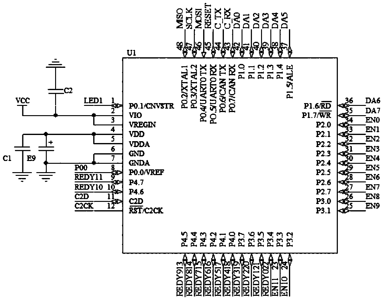
[0025] 45, 46, 47, 48 are SPI function pins, which are connected with the SPI function pins of the magnetic drive chip. The layout of the magnetoresistive sensor array is 10 rows and 20 columns, and a total of 200 points form a matrix. Each point requires two IO signals, chip select and data waiting signals. The controller controls each sensor separately through a logic device. Pins 43 and 44 of C8051F500-IQ are CAN bus communication pins, which are connected with pins 3 and 4 of the CAN driver.
Login to View More PUM
 Abstract
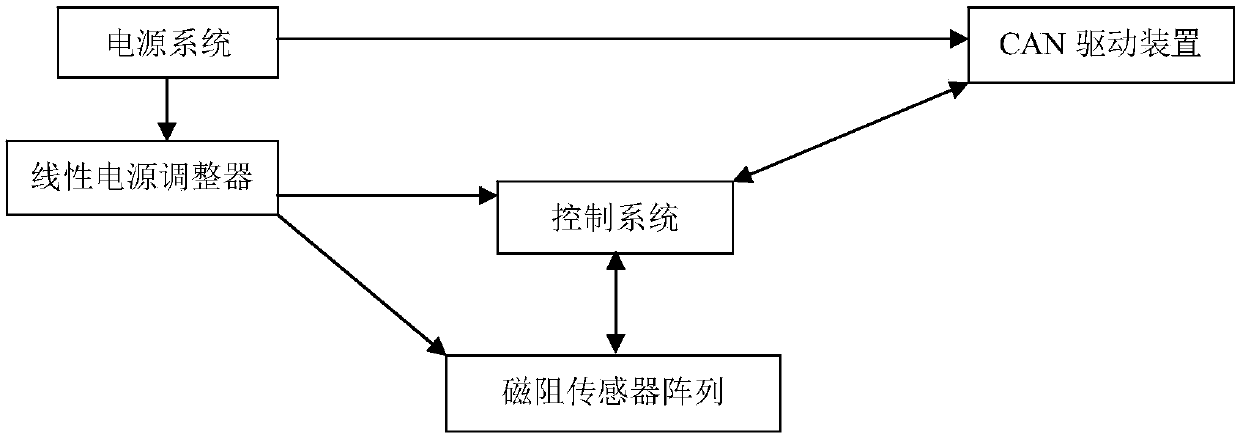
The invention relates to an array magnetic navigation sensor, and the sensor comprises a magnetoresistive sensor array which is connected with a control system, collects a magnetic field signal and sends the magnetic field signal to the control system; the control system which is connected with a CAN driving device and used for converting the magnetic field signal into two-dimensional position information and sending the two-dimensional position information to the CAN driving device; the CAN driving device which is connected with an upper computer through a CAN bus and sends the two-dimensional position information to the upper computer; and a power supply system which is connected with the CAN driving device to supply power to the CAN driving device, and is connected with the control system and the magnetoresistive sensor array through a linear power supply adjuster to supply power to the CAN driving device. The sensor can improve the detection precision of the magnetic field, can detect the deviation in the left-right direction, also can detect the deviation in the front-back direction, improves the walking precision of the AGV, and reduces the interference of an external electromagnetic field on signals. The wiring structure is more flexible and convenient.
Description
technical field [0001] The invention relates to the field of magnetic field detection, in particular to an array magnetic navigation sensor. Background technique [0002] Most of the existing magnetic navigation sensors detect the magnetic field in a one-dimensional way. This detection method can only judge the magnetic field deviation in one direction. When the positioning accuracy of the AGV system is higher, it cannot meet the requirements of the AGV system. Most of the signal interface methods are IO or analog. The IO mode needs to occupy the interface resources of the control system, and the wiring layout is also very cumbersome. The analog method can only judge simple magnetic field signals. When there are multiple magnetic fields or different polarities, it is more difficult to judge, and the analog signal is easily interfered by external electromagnetic signals, and the signal output is unstable. Contents of the invention [0003] Aiming at the deficiencies of th...
Claims
Login to View More Application Information
Patent Timeline
 Patent Type & AuthorityApplications(China)
IPC IPC(8): G01C21/20G01R33/09
Inventor张雷汪洵魏星曹智荀于焕
OwnerSHENYANG SIASUN ROBOT & AUTOMATION