Eureka AIR delivers breakthrough ideas for toughest innovation challenges, trusted by R&D personnel around the world.

Differential photoacoustic measurement system and method with temperature compensation

A technology of temperature compensation and photoacoustic measurement, which is applied in the direction of measuring devices, material analysis through optical means, instruments, etc., can solve the problem that the influence of the temperature change of the measured liquid cannot be suppressed, the two photoacoustic signals cannot be guaranteed completely, and the light intensity can be eliminated The impact of the problem, to achieve consistency and interchangeability requirements are not high, to meet blood glucose monitoring, improve the effect of accuracy

Active Publication Date: 2021-04-27
SHANGHAI JIAOTONG UNIV
View PDF11 Cites 0 Cited by
  • Summary
  • Abstract
  • Description
  • Claims
  • Application Information

AI Technical Summary

Problems solved by technology

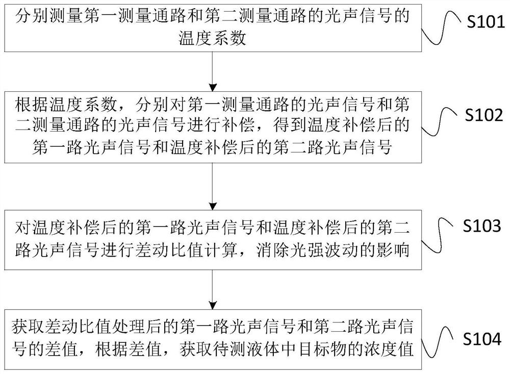
[0005] However, there are some obvious problems in these methods: First, the two photoacoustic signals cannot be guaranteed to be completely consistent, and it is not difficult to fundamentally eliminate the influence of light intensity through subtraction.
Second, the liquids in the two photoacoustic cells are different, and the temperature will also be different, and the influence caused by the temperature change of the measured liquid cannot be suppressed.

Method used


Image

  • Differential photoacoustic measurement system and method with temperature compensation
  • Differential photoacoustic measurement system and method with temperature compensation
  • Differential photoacoustic measurement system and method with temperature compensation

Examples


Embodiment Construction

[0037] The present invention will be described in detail below in conjunction with specific embodiments. The following examples will help those skilled in the art to further understand the present invention, but do not limit the present invention in any form. It should be noted that those skilled in the art can make several changes and improvements without departing from the concept of the present invention. These all belong to the protection scope of the present invention.

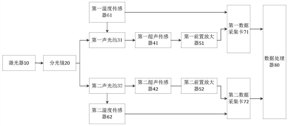
[0038] figure 1 A schematic structural diagram of a differential photoacoustic measurement system with temperature compensation provided for Embodiment 1 of the present invention, as shown in figure 1As shown, the system of this embodiment may include: a laser 10, a beam splitter 20, a first photoacoustic cell 31, a second photoacoustic cell 32, a first ultrasonic sensor 41, a second ultrasonic sensor 42, and a first preamplifier 51 , the second preamplifier 52, the first temperature sensor 61, the sec...


PUM


Abstract

The present invention provides a differential photoacoustic measurement system and method with temperature compensation, including: a first measurement path for measuring the photoacoustic signal of the liquid to be measured, and a second measurement path for measuring the photoacoustic signal of the reference liquid pass; the first temperature sensor for measuring the first temperature signal corresponding to the first photoacoustic cell in the first measurement path, and the second temperature for measuring the second temperature signal corresponding to the second photoacoustic cell in the second measurement path sensor; the first data acquisition card for collecting the photoacoustic signal of the liquid to be tested and the first temperature signal; the second data acquisition card for collecting the photoacoustic signal of the reference liquid and the second temperature signal; the data processor is used to The photoacoustic signal of the liquid to be tested and the photoacoustic signal of the reference liquid are compensated for the collected data in the first data collection card and the second data collection, to obtain the concentration value of the target substance in the liquid to be tested. The invention can effectively eliminate the influence of temperature and light intensity fluctuations on the measurement results, and improve the measurement accuracy.

Description

technical field [0001] The invention relates to the technical field of biological monitoring, in particular to a differential photoacoustic measurement system and method with temperature compensation. Background technique [0002] Non-invasive blood glucose detection methods have become the development trend in the field of blood glucose detection due to less pain for patients, low chance of infection, and continuous monitoring of blood glucose changes. At present, the main non-invasive detection methods of blood glucose mainly include near-infrared spectroscopy, fluorescence spectroscopy, and photoacoustic spectroscopy. Among them, photoacoustic spectroscopy has become one of the most promising methods for clinical diagnosis and treatment due to its high sensitivity and good specificity. [0003] Photoacoustic spectroscopy is an important branch of spectroscopy. It is a new method of spectral analysis that integrates the principles and technologies of light, heat, sound, a...

Claims


Application Information

Patent Timeline
Patent Type & Authority Patents(China)
IPC IPC(8): G01N21/01G01N21/17
Inventor 赵辉陶卫吕娜吕鹏飞陆志谦何巧芝王倩
Owner SHANGHAI JIAOTONG UNIV
Why Eureka
Eureka Blog
Learn More