

Vehicle projection system
A technology of a projection system and a projection module, which is applied in the field of vehicle projection lighting and mechanical engineering, can solve the problems that it is difficult to change the irradiation image, cannot display dynamic images, and limits the realization of the function of the vehicle projection system, and achieves good imaging quality, small field curvature and Distortion, high resolution effects
- Summary
- Abstract
- Description
- Claims
- Application Information
AI Technical Summary
Problems solved by technology
Method used
Image

Examples
Embodiment 1
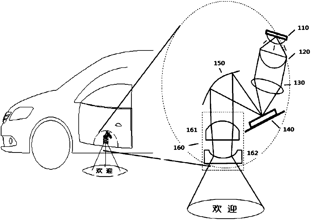
[0048] refer to figure 2 A vehicle-mounted projection system according to Embodiment 1 of the present application will be specifically described. figure 2 A schematic structural diagram of a vehicle-mounted projection system according to Embodiment 1 of the present application is shown.
[0049] Such as figure 2 As shown, in this exemplary embodiment, a high-brightness LED light source 110 emits a light beam for illumination, and the light beam first enters a light adjustment mechanism including a collimator lens 120 and a relay lens 130 . Wherein, the collimating lens 120 is used to collimate the light beam emitted from the high-brightness LED light source 110 and propagate along a straight line, and the relay lens 130 is used to shape the light beam to uniformly irradiate the subsequent dynamic image display device. However, the light adjustment mechanism is not limited to the combination of the collimator lens 120 and the relay lens 130 described above, as long as the ...
Embodiment 2
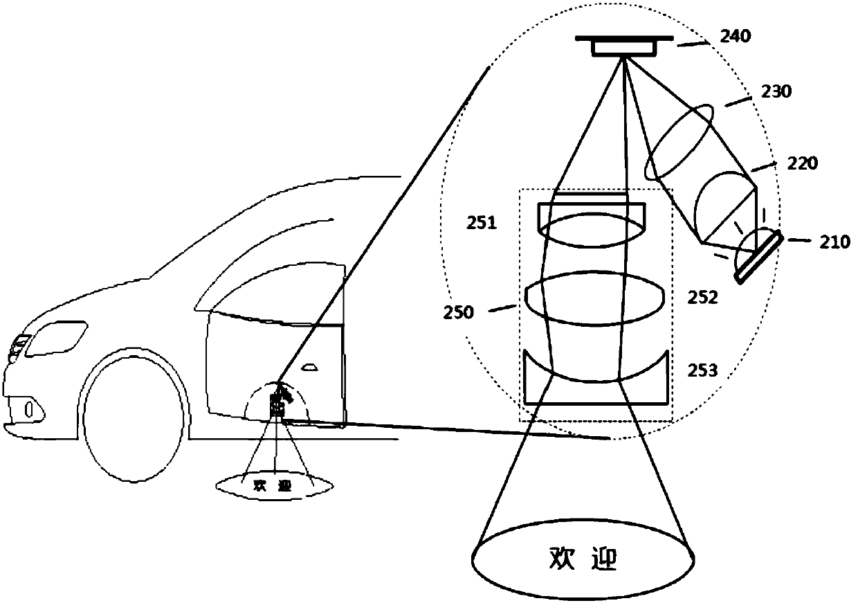
[0055] refer to image 3 A vehicle-mounted projection system according to Embodiment 2 of the present application will be specifically described. image 3 is a schematic configuration diagram showing a vehicle-mounted projection system according to Embodiment 2 of the present application.
[0056] Such as image 3 As shown, the high-brightness LED light source 210 emits a light beam for illumination, and the light beam first enters the light adjustment mechanism including the collimator lens 220 and the relay lens 230 . The collimator lens 220 and the relay lens 230 are sequentially arranged along the optical path direction of the light beam propagating. Wherein, the collimating lens 220 is used to collimate the light beam emitted from the high-brightness LED light source 210 and propagate along a straight line, and the relay lens 230 is used to shape the light beam to uniformly irradiate the dynamic image display device. However, the light adjustment mechanism is not limit...
Embodiment 3
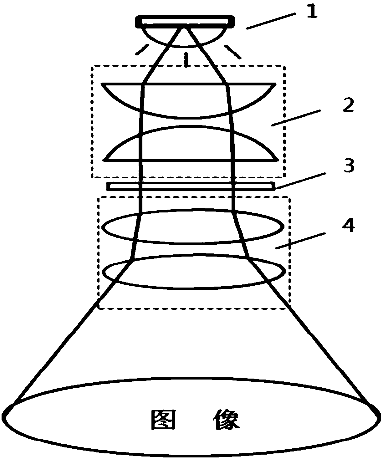
[0063] refer to Figure 4 A vehicle-mounted projection system according to Embodiment 3 of the present application will be specifically described. Figure 4 is a schematic configuration diagram showing a vehicle-mounted projection system according to Embodiment 3 of the present application.
[0064] Such as Figure 4 As shown, a high-brightness LED light source 310 emits a light beam for illumination.
[0065] In this exemplary embodiment, a fly-eye lens 320 is used as the light adjustment mechanism. The fly-eye lens is formed by a series of small lenses, which converge each beam of parallel light (with uneven intensity distribution) emitted by the light source. Applying the double-row fly-eye lens array to the lighting system can obtain high light energy utilization efficiency and uniform lighting of a large area. Fly-eye lenses have broad application prospects in the fields of microdisplays and projection displays. The fly-eye lens 320 makes the light beam emitted from ...
PUM
 Abstract
Description
Claims
Application Information