A method for automatically stitching images by adjusting the height of an X-ray detector

A height-adjusting, automatic splicing technology, applied in image enhancement, image data processing, instruments, etc., can solve the problems of large amount of calculation and error-prone splicing, and achieve the effect of reducing difficulty, facilitating correctness, and ensuring the effect

Active Publication Date: 2021-02-26
晓智未来(成都)科技有限公司
View PDF14 Cites 0 Cited by
  • Summary
  • Abstract
  • Description
  • Claims
  • Application Information

AI Technical Summary

Problems solved by technology

This completely algorithm-based splicing method has a large amount of calculations, and splicing is prone to errors

Method used


Image

  • A method for automatically stitching images by adjusting the height of an X-ray detector
  • A method for automatically stitching images by adjusting the height of an X-ray detector
  • A method for automatically stitching images by adjusting the height of an X-ray detector

Examples


Embodiment 1

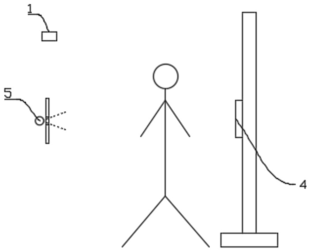
[0037] Such as Figure 1-Figure 6 As shown, this embodiment provides a method for automatic image stitching by adjusting the height of the X-ray detector, including the following steps:

[0038] S1. Calculating the three-dimensional coordinates of the joint points: the binocular camera 1 located in front of the detection position acquires the RGBD image of the human body on the detection position, and obtains the three-dimensional coordinates of the joint points of the human body through calculation. The three-dimensional coordinates of the joint points include the three-dimensional coordinates of the human shoulder joint points 2 and Three-dimensional coordinates of other joint points of several human bodies;

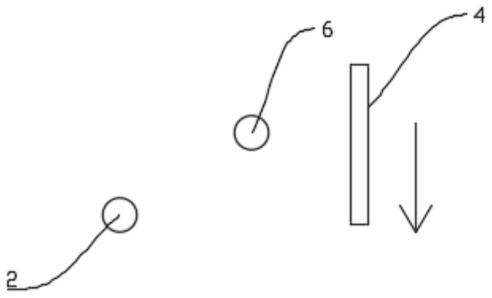
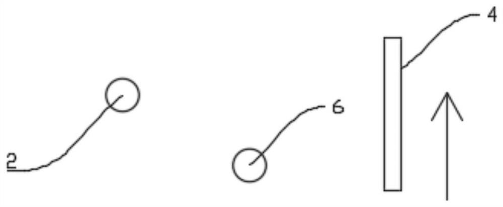
[0039] S2. Calculating the coordinate offset: subtracting the longitudinal coordinate value of the human shoulder joint point 2 from the preset longitudinal coordinate value of the shoulder joint point to obtain the coordinate offset;

[0040] S3. Initial position pos...

Embodiment 2

[0045] This embodiment is optimized and defined on the basis of the above-mentioned embodiment 1.

[0046] In S1:

[0047] S1.1. Use the binocular camera 1 to shoot the scene at the detection position, collect the RGBD image information of the human body at the detection position, and process the RGBD image information through the processor to obtain an RGB image and a depth image. The depth image includes Image information and depth of field information;

[0048] S1.2. Calculate the positions of several human joint points in the depth image based on the deep learning model of human body joint point detection, and determine the joint point image coordinates of several human body joint points in the depth image;

[0049] S1.3. Calculate the three-dimensional coordinates of the joint points corresponding to the joint point image coordinates according to the joint point image coordinates, the depth of field information and the preset calibration parameters of the binocular camer...

Embodiment 3

[0053] This embodiment is optimized and defined on the basis of the above-mentioned embodiment 1.

[0054] In S6:

[0055] S6.1. Determine alignment point 8: alignment point 8 is joint point 1 8.1 and joint point 2 8.2 in image A 10 and joint point 3 and joint point 4 in image B 11, joint point 1 8.1 and joint point 3 are the human body The same joint point, joint point 2 8.2 and joint point 4 are the same joint point of the human body;

[0056] S6.2. Alignment point 8 matching: joint point 1 8.1 is coincident with joint point 3, joint point 2 8.2 is coincident with joint point 4, and a rectangular overlapping area 9 is obtained;

[0057] S6.3. Perform image fusion on the rectangular overlapping area 9 to obtain a new A image 10. The A image 10 and the next B image 11 continue the splicing steps of the above S6.1 and S6.2 until all the images are completely relied on .


PUM


Abstract

The invention belongs to the technical field of digital image processing, and specifically relates to a method for automatically splicing images by adjusting the height of an X-ray detector, S1, calculating three-dimensional coordinates of joint points; S2, calculating coordinate offsets; S3, positioning initial positions; S4, determining Move the coordinates of the reference point; S5, shifting successively and taking images; S6, image splicing; a method for automatically splicing images by adjusting the height of an x-ray detector provided by the present invention, by detecting the joint points of the human body, the distance between the two images can be known The position and size of the overlapping part can realize the matching and splicing of the two images, and the image splicing is easier.

Description

technical field [0001] The invention belongs to the technical field of digital image processing, and in particular relates to a method for automatically splicing images by adjusting the height of an X-ray detector. Background technique [0002] In the original image chain, the X light source, the center of the light beam, and the center of the flat panel detector are located on the same straight line, the position is relatively fixed and there is only one degree of freedom (moving up and down), and the conical beam emitted by the X light source passes through the light beam. A beam of specific shape and size is formed, which passes through the object to be photographed and is received by a flat panel detector located behind the object. [0003] For the needs of image diagnosis, the information of the entire human spine is usually required, and the flat panel detector can only obtain part of the information at a time. In order to present complete spine information on one ima...

Claims


Application Information

Patent Timeline
Patent Type & Authority Patents(China)
IPC IPC(8): G06T5/50
Inventor 何香颖张军侯雨舟
Owner 晓智未来(成都)科技有限公司
Why Eureka
Try Eureka