Tubular pump-free suction mechanism

An absorption mechanism and tube-type technology, applied in the direction of dust removal, cleaning methods and utensils, chemical instruments and methods, etc., can solve the problems of poor foundation for popularization and application, inapplicability of small-caliber barrels, high suction force requirements, etc., to achieve Reasonable layout, good environmental protection benefits, and compact structure

Pending Publication Date: 2019-07-02
丹阳市延陵镇弘理木材厂
View PDF0 Cites 0 Cited by
  • Summary
  • Abstract
  • Description
  • Claims
  • Application Information

AI Technical Summary

Problems solved by technology

[0002] In the prior art, when changing the water for fish tanks, or when taking gasoline and diesel oil for vehicles or changing barrels, people usually use a catheter to insert one end into the water or the oil barrel, and then suck it with their mouths. At the other end of a conduit, water or oil will flow along the conduit; the key point of this method is that when people suck water or oil with their mouths, it is often too late for people to leave the mouth of the conduit, and the water or oil flowing out along the conduit is very fast. Easy to flow into the mouth, very unhygienic
Based on the above shortcomings, a water and oil suction pipe that is sucked by a pump has been developed. Although this technology solves the defects of the mouth suction type, the volume of the pump is relatively large, resulting in an increase in the volume of the water and oil suction pipe, which is not suitable for On the other hand, the price of the pump also increases the cost of water and oil suction pipes, and the basis for its promotion and application is also poor, and this kind of pipes mostly use right-angle pipes, which require more suction force for water flow. high
Moreover, the traditional pipeline is generally a single-pass type, and its working efficiency is low.

Method used


Image

  • Tubular pump-free suction mechanism

Examples


Embodiment Construction

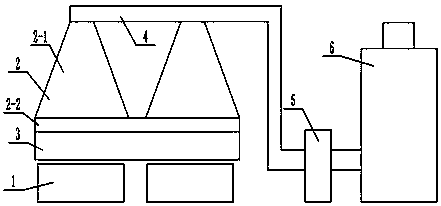
[0009] Depend on figure 1 Known, the present invention a kind of tube-type non-pump absorption mechanism, is made up of pickling tank 1, square cone body cover 2, drooping soft board 3, mist suction tube 4, anti-corrosion induced draft fan 5, treatment tower 6, pickling tank 1 is installed On the ground, the square cone body cover 2 is arranged directly above the pickling tank 1, and the mist suction pipe 4 is arranged on the top of the square cone body cover 2 and is connected thereto. The other end is connected to the processing tower 6. The square cone cover 2 is composed of a mist guide slant plate 2-1 and a fog storage plate 2-2. The square pyramidal structure, the fog storage plate 2-2 is arranged on the lower four sides of the square pyramidal structure, the outer side of the fog storage plate 2-2 is provided with a drooping soft board 3, and the two square pyramidal body covers 2 are connected in series through the mist suction pipe 4, and the plurality of square cone...


PUM


Abstract

The invention discloses a tubular pump-free suction mechanism. The mechanism consists of a pickling tank, a square cone cover, drooping soft plates, a mist suction pipe, an anti-corrosion induced draft fan and a treatment tower, wherein the pickling tank is installed on the ground, the square cone cover is arranged right above the pickling tank and communicates with the pickling tank, the mist suction pipe is arranged above the square cone cover, one end of the anti-corrosion induced draft fan is connected with an outlet of the mist suction pipe, and the other end of the anti-corrosion induceddraft fan is connected with the treatment tower. The mechanism is characterized in that drooping soft plates are arranged around the outer side of a mist storage plate. According to the invention, acid-base mist is sucked through series connection and parallel connection, and the mechanism has the advantages of low power, thorough suction, energy consumption cost reduction and energy conservation.

Description

technical field [0001] The invention relates to a water-absorbing or oil-absorbing pipe, specifically, a pipe-type pumpless absorbing mechanism. Background technique [0002] In the prior art, when changing the water for fish tanks, or when taking gasoline and diesel oil for vehicles or changing barrels, people usually use a catheter to insert one end into the water or the oil barrel, and then suck it with their mouths. At the other end of a conduit, water or oil will flow along the conduit; the key point of this method is that when people suck water or oil with their mouths, it is often too late for people to leave the mouth of the conduit, and the water or oil flowing out along the conduit is very fast. It easily flows into the mouth and is very unhygienic. Based on the above shortcomings, a water and oil suction pipe that is sucked by a pump has been developed. Although this technology solves the defects of the mouth suction type, the volume of the pump is large, resulti...

Claims


Application Information

Patent Timeline
Patent Type & Authority Applications(China)
IPC IPC(8): B08B15/02B08B13/00
CPCB08B13/00B08B15/02
Inventor 杨云祥
Owner 丹阳市延陵镇弘理木材厂
Why Eureka
Try Eureka