Hardware stamping and cutting equipment

A cutting equipment, hardware technology, applied in the direction of metal processing equipment, welding equipment, laser welding equipment, etc., can solve the problems of debris easily scattered to the outside environment of the machine, uneven cutting surface, prone to vibration, etc., to achieve good reduction Shock effect, good vibration isolation effect, not easy to deform

Inactive Publication Date: 2019-07-02
涟水县金泽电子科技有限公司
View PDF0 Cites 0 Cited by
  • Summary
  • Abstract
  • Description
  • Claims
  • Application Information

AI Technical Summary

Problems solved by technology

[0003] However, the existing hardware cutting machine is prone to problems such as uneven cutting surface and gaps during cutting, and the cutting machine is prone to problems such as vibration due to the high cutting force during work, and the cutting machine will produce debris during cutting. Debris is easy to disperse to the outside of the machine to cause environmental pollution

Method used


Image

  • Hardware stamping and cutting equipment
  • Hardware stamping and cutting equipment
  • Hardware stamping and cutting equipment

Examples


Embodiment Construction

[0019] The following will clearly and completely describe the technical solutions in the embodiments of the present invention with reference to the accompanying drawings in the embodiments of the present invention. Obviously, the described embodiments are only some, not all, embodiments of the present invention. Based on the embodiments of the present invention, all other embodiments obtained by persons of ordinary skill in the art without making creative efforts belong to the protection scope of the present invention.

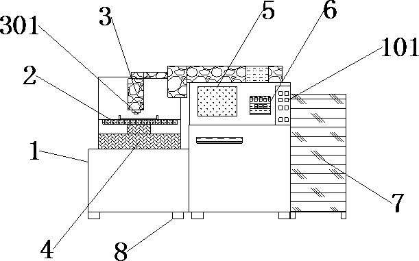
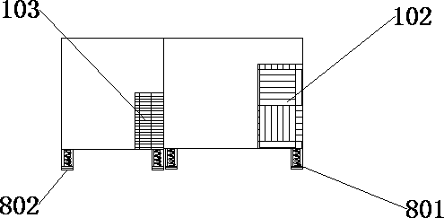
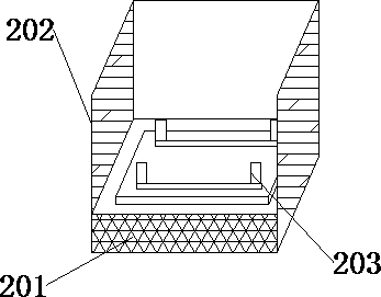
[0020] see Figure 1-3 , the present invention provides a technical solution: a metal stamping and cutting equipment, including a device body 1, a workbench 2 and a laser cutting machine 3, the middle part of the left side of the device body 1 is provided with a workbench 2, and the workbench 2 and the device body 1 Fixed connection, a laser cutting machine 3 is provided above the device body 1, the laser cutting machine 3 is embedded in the device body 1, a m...


PUM


Abstract

The invention discloses hardware stamping and cutting equipment. The equipment comprises a device body, a workbench and a laser cutting machine, wherein a workbench is arranged in the middle of the left side of the device body, the workbench is fixedly connected with the device body, the laser cutting machine is arranged above the device body, the laser cutting machine is embedded in the device body, a measuring table is arranged on the upper surface of the device body, and the measuring table is embedded in the device body. A dust cover and a dust collecting box are arranged in the workbench,chippings and dust generated by cutting can be isolated through the dust cover, so that the phenomenon that the chippings and the dust are diffused to the outside, and the environment pollution is caused is avoided, the chippings fall into the dust collecting box after being blocked by a baffle of the dust cover, the dust collecting box can be used for collecting the chippings after cutting so asto prevent the chippings from causing environmental pollution, in addition, the dust collecting box of a stainless steel material has very high heat resistance, so that the influence on the dust collecting box caused by the chippings at high temperature can be avoided.

Description

technical field [0001] The invention relates to the technical field of metal cutting equipment, in particular to a metal stamping and cutting equipment. Background technique [0002] During the manufacturing process of hardware components, there will be problems of different lengths and sizes. Therefore, it is necessary to cut by a metal cutting machine to make the shape and size of the hardware components consistent. With the development of the modern mechanical processing industry, the quality and accuracy of cutting are required With the continuous improvement, the requirements for improving production efficiency, reducing production costs, and highly intelligent automatic cutting functions are also increasing. The development of metal cutting machines must adapt to the requirements of the development of modern mechanical processing industry. [0003] However, the existing hardware cutting machine is prone to problems such as uneven cutting surface and gaps during cutting...

Claims


Application Information

Patent Timeline
Patent Type & Authority Applications(China)
IPC IPC(8): B23K26/38B23K26/70
CPCB23K26/38B23K26/70B23K26/702
Inventor 宋海霞
Owner 涟水县金泽电子科技有限公司
Why Eureka
Try Eureka