
Flange assembly of sterile glove

A glove and flange technology, which is applied in the field of flange components of sterile gloves, can solve the problems of inability to test glove integrity, prolong the production cycle, and flanges that cannot be used universally, so as to reduce procurement costs, increase production batches, and achieve versatility Good results

Pending Publication Date: 2019-07-02
TRUKING TECH LTD
View PDF0 Cites 0 Cited by
  • Summary
  • Abstract
  • Description
  • Claims
  • Application Information

AI Technical Summary

Problems solved by technology

Currently on the market, the glove flange of the operation box for the O-RABS system and the two types of glove flanges for the isolator cannot be used in common, and they are three different products.
However, some O-RABS systems require gloves to be tested for integrity, and the flanges of ordinary sterile gloves do not have airtightness, so the integrity of gloves cannot be tested; when some isolator products are used to produce different drugs, The glove flange of the operation box is not shared and needs to be replaced, which is not only troublesome to replace, but also requires additional sterilization and storage of the replaced glove flange, which prolongs the production cycle and increases the cost

Method used


Image

  • Flange assembly of sterile glove
  • Flange assembly of sterile glove
  • Flange assembly of sterile glove

Examples


Embodiment 1

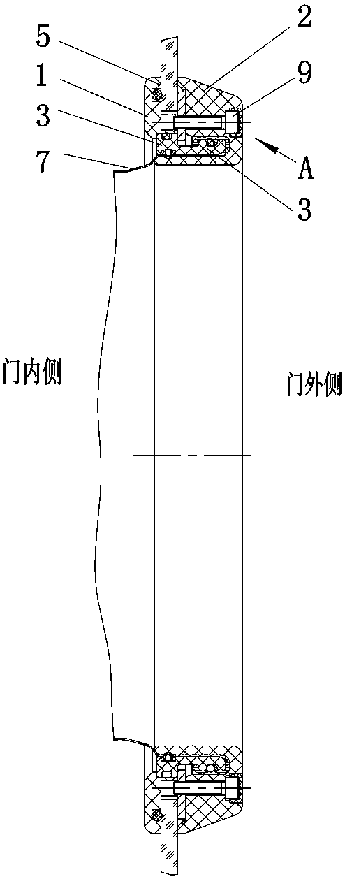
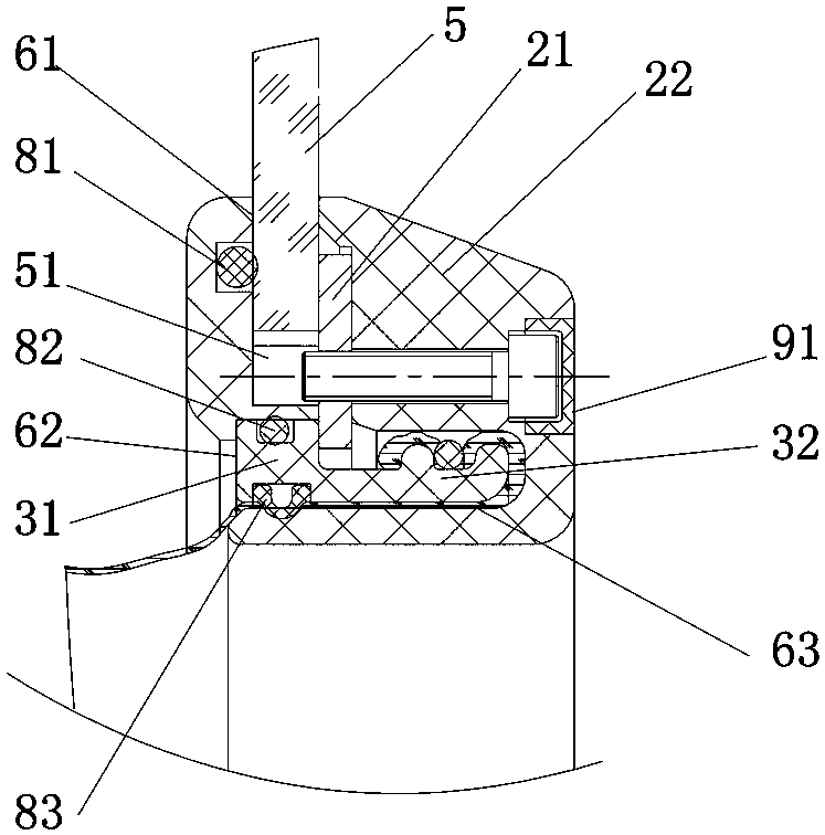
[0034] Such as Figure 1 to Figure 4 As shown, the flange assembly of the sterile glove of the present embodiment includes a first jacket 1, a second jacket 2 and a glove flange 3, and the glove flange 3 includes a fixing part 31 and a handle for installing a sterile glove 7. The glove installation part 32, the first jacket 1 and the second jacket 2 are connected by fasteners 4 to form a first annular groove 61 where the glass door 5 is clamped and a second annular groove 62 where the fixing part 31 is embedded. The jacket 2 is provided with a third annular groove 63 for accommodating the glove mounting portion 32 .

[0035] In a specific application example, the glove installation part 32 may face the first jacket 1 or the second jacket 2. In this embodiment, the glove installation part 32 faces the second jacket 2 and is located in the third annular groove 63 Inside, and the fixing part 31 is supported on the side wall of the third annular groove 63 to ensure that the glove...

Embodiment 2

[0046] Such as Figure 5 and 6 As shown, the flange assembly of the sterile glove of this embodiment is basically the same as that of Embodiment 1, the only difference being:

[0047] In this embodiment, the first jacket 1 is arranged on the outside of the glass door 5 , and the second jacket 2 is arranged on the inside of the glass door 5 . In this way, the second jacket 2 with a larger thickness is arranged on the inside of the glass door 5, and the first jacket 1 with a smaller thickness is arranged on the outside of the glass door 5, which not only occupies a small space, but also is beautiful.

Embodiment 3

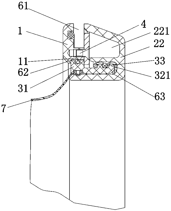
[0049] Such as Figures 7 to 9 As shown, the flange assembly of the sterile glove of this embodiment is basically the same as that of Embodiment 1, the only difference being:

[0050] In this embodiment, the glove installation part 32 is installed in the second annular groove 62 facing the first jacket 1 .

[0051] In this embodiment, the replacement of sterile gloves 7 is an internal replacement type. The replacement process is as follows: first put the sterilized new sterile gloves 7 into the isolator from the sterile inlet, and pass them to the old sterile gloves 7 to be replaced in the isolator; then put the old sterile gloves 7 Pull out to the outermost groove of the glove installation part 32, put the new sterile glove 7 on the old sterile glove 7, and place it in the innermost groove of the glove installation part 32; The old sterile gloves 7 are torn off and taken out from the new sterile gloves 7, and the replacement is completed. This replacement method is suitabl...


PUM


Abstract

The invention discloses a flange assembly of a sterile glove. The flange assembly comprises a first jacket, a second jacket and the glove flange, wherein the glove flange comprises a fixing portion and a glove mounting portion, the first jacket and the second jacket are connected through fasteners to form a first annular groove which is clamped with a glass door and a second annular groove which is embedded in the fixing portion, and the second jacket sleeves a third annular groove for containing the glove mounting portion. According to the flange assembly, the glove flange can be installed inwards and can be installed outwards, the first jacket and the second jacket can be arranged in an interchange mode, and the sterile glove can be replaced inside and outside, so that the multi-functionand multi-working-condition requirements can be met, the requirements of various different drug production processes are met, and the flange assembly can be applied to an O-RABS system and can also be used as an isolator system.

Description

technical field [0001] The invention relates to the field of pharmaceutical machinery and equipment, in particular to a flange assembly of sterile gloves. Background technique [0002] At present, there are various kinds of operation box gloves, one is the operation box glove flange for O-RABS system, and the other is the operation box glove flange for isolator (or isolation box). There are two types of glove flanges for isolators. One is to change gloves inside, and the old gloves are taken out from the flange opening; the other is to change gloves outside, and the old gloves are kept in the operation box and taken out from other safety ports. At present, the glove flange of the operation box for the O-RABS system on the market and the two types of glove flanges for the operation box used by the isolator cannot be used in common, and they are three different products. However, some O-RABS systems require gloves to be tested for integrity, and the flanges of ordinary steril...

Claims


Application Information

Patent Timeline
Patent Type & Authority Applications(China)
IPC IPC(8): F16B1/02F16J15/06B25J21/02
CPCF16B1/02F16J15/062B25J21/02
Inventor 刘志戴晓坚
Owner TRUKING TECH LTD
Learn More