
Distance measuring device

A distance measurement and distance technology, which is applied in the field of optical distance measurement devices, can solve the problems that the device is susceptible to interference, the reliability and accuracy of distance measurement, etc., so as to reduce the interference density gradient or air-liquid transition, improve measurement reliability, The effect of improving measurement accuracy

Active Publication Date: 2019-07-02
PRECITEC OPTRONIK GMBH
View PDF12 Cites 0 Cited by
  • Summary
  • Abstract
  • Description
  • Claims
  • Application Information

AI Technical Summary

Problems solved by technology

However, such devices are susceptible to interference, whereby the reliability and accuracy of distance measurements suffer

Method used


Image

  • Distance measuring device
  • Distance measuring device
  • Distance measuring device

Examples


Embodiment Construction

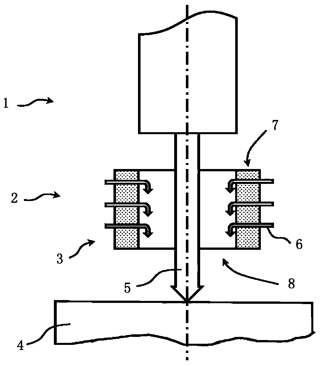
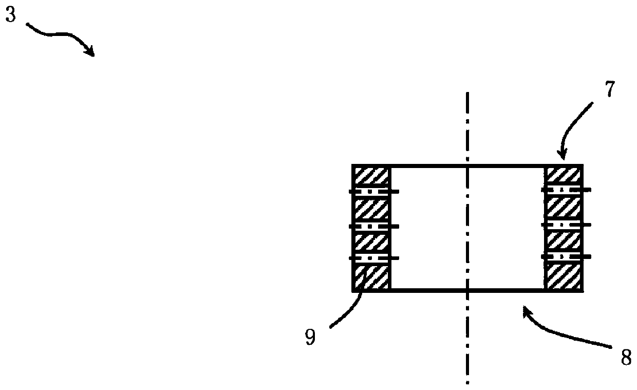
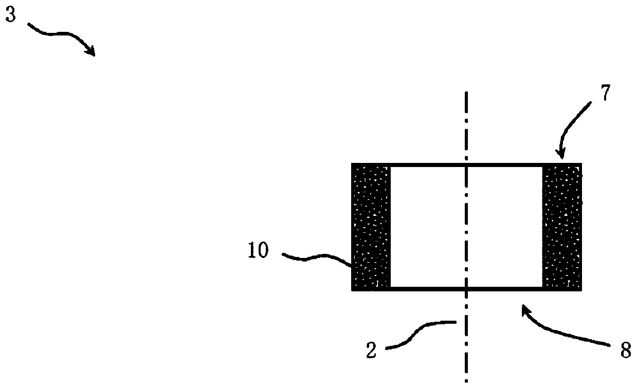
[0085] figure 1 A measurement configuration of a distance measuring device according to an embodiment is schematically shown. figure 1 In particular, an optical measuring system 1 is shown for carrying out an optical measuring method, a liquid guide 2 with a flow element 3 and a measuring object 4 on which the optical measuring method can be carried out. In addition, in figure 1 The measuring beam 5 extending from the optical measuring system 1 to the measuring object 4 is symbolically shown by a wide arrow in . The measuring beam 5 is formed by the optical measuring system 1 from broadband measuring light originating from a broadband light source (not shown). In addition, in figure 1 The flow lines 6 are shown in the form of curved arrows to illustrate the liquid flow.

[0086] exist figure 1 In the example shown in , the optical measurement system 1 is configured to perform a color distance measurement method. In other embodiments, the optical measurement system may be...


PUM


Abstract

The application discloses a distance measuring device. The distance measuring device comprises a measuring head 20, the measuring head 20 having an optical measuring system 1 for carrying out an optical measurement process on a measurement object 4 by means of at least one measuring light beam 5 formed from a broad-band measuring light. The measuring head 20 further has a liquid guide 2 with a liquid inlet 28 and a liquid outlet 27 for producing a jet of liquid directed at the measurement object 4, the liquid guide 2 being designed such that in certain sections at least the measuring light beam 5 runs essentially along the jet of liquid. The measuring head 20 further has a flow element 3 with a laminar flow channel 8, the flow element 3 being designed such that the at least one measuring light beam 5 is able to reach the measurement object 4 by passing through the laminar flow channel 8.

Description

technical field [0001] The invention relates to an optical distance measuring device, in particular an optical distance measuring device operating with a broadband light source, and a corresponding distance for measuring distances or distance differences, in particular for thickness monitoring of semiconductor wafers during thinning of semiconductor wafers Measurement methods. Background technique [0002] Optical distance measuring devices with broadband light sources are known which enable the determination of distances or distance differences to the upper or boundary surface of the sample or between the upper surface and the boundary surface of the sample from the reflection spectrum of broadband light. In such distance measuring devices based on the determination of the reflection spectrum of broadband light, depending on the measurement method used, between distance measurements using OCT (Optical Coherence Tomography) or using spectral interference configurations and t...

Claims


Application Information

Patent Timeline
Patent Type & Authority Applications(China)
IPC IPC(8): G01B11/06G01B9/02H01L21/66
CPCG01B11/06G01B9/02027G01B9/02077H01L22/12G01B11/0608G01B2210/50B24B7/228B24B49/12G01B11/026G01B9/02001G01S17/48
Inventor C·迪茨
Owner PRECITEC OPTRONIK GMBH
Learn More