Nuclear fusion first wall capable of preventing temperature of part directly facing plasma from being too high

A plasma and high-temperature technology, applied in the field of nuclear fusion first wall, can solve the problems of high heat flux density and high temperature

Inactive Publication Date: 2019-07-02
HARBIN INST OF TECH
View PDF6 Cites 1 Cited by
  • Summary
  • Abstract
  • Description
  • Claims
  • Application Information

AI Technical Summary

Problems solved by technology

[0004] In order to solve the problem that the temperature of the part facing the plasma of the existing nuclear fusion first wall is too high due to excessive heat flux, the prese

Method used


Image

  • Nuclear fusion first wall capable of preventing temperature of part directly facing plasma from being too high
  • Nuclear fusion first wall capable of preventing temperature of part directly facing plasma from being too high

Examples


Example Embodiment

[0016] Embodiment 1

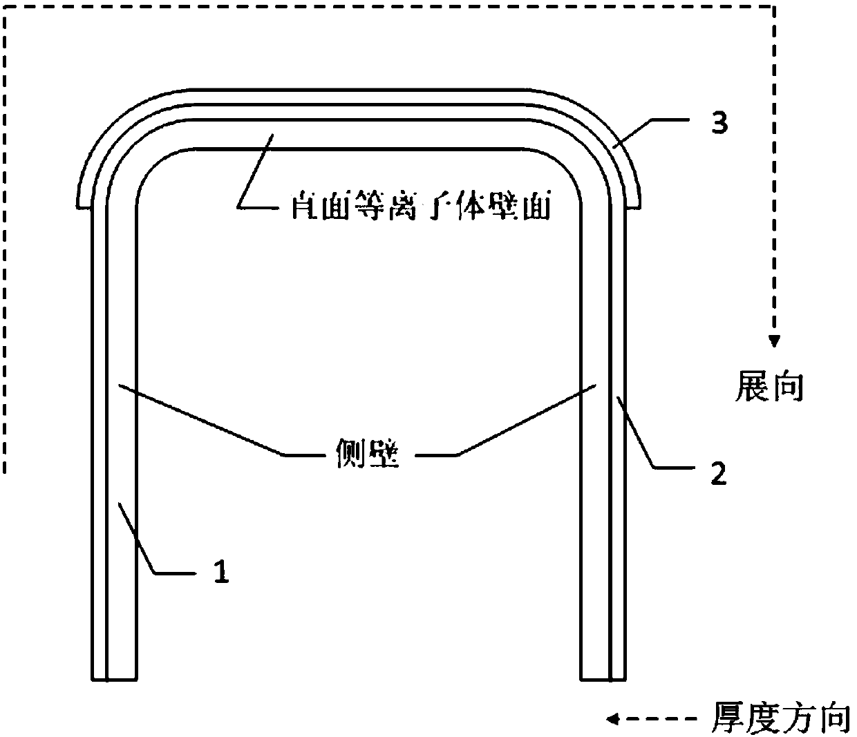
[0017] combine figure 1 This embodiment is described. In this embodiment, a first wall of nuclear fusion that prevents the temperature of the part facing the plasma from being too high is covered. Material layer 2; the outer surface of the material layer 2 is further provided with a uniform protective layer 3 on the wall surface facing the plasma.

[0018] like figure 1 As shown, in the present invention, "span direction" means that the material layer 2 is developed into a horizontal plane, and the thermal conductivity along the direction of the plane (surface of the material layer 2) is the spanwise thermal conductivity, and "in the thickness direction" refers to the direction from the material The direction from the outer wall to the inner wall of layer 2 or from the inner wall to the outer wall.

[0019] like figure 1 As shown in the figure, during the operation of the nuclear fusion reactor, the part of the first wall directly facing the plasma ca...

Example Embodiment

[0022] Embodiment 2

[0023] This embodiment further defines the material layer 2 in the first embodiment, and the material of the material layer 2 in this embodiment is a synthetic graphite sheet.

[0024] In the present embodiment, the material layer 2 adopts synthetic graphite sheet, which is an existing product, and the use of synthetic graphite sheet can obtain the effect that the thermal conductivity in the expansion direction is higher than the thermal conductivity along the thickness direction.

Example Embodiment

[0025] Embodiment 3

[0026] This embodiment further defines the material layer 2 in the first or second embodiment, and the thickness of the material layer 2 in this embodiment is 0.017 mm˜0.050 mm.

[0027] In this embodiment, the thickness of the material layer 2 can be any value in the range of 0.017 mm to 0.050 mm, and the thickness within this range can obtain a higher extensional thermal conductivity.


PUM

PropertyMeasurementUnit
Thicknessaaaaaaaaaa
Thicknessaaaaaaaaaa

Abstract

The invention discloses a nuclear fusion first wall capable of preventing temperature of a part directly facing plasma from being too high, and belongs to the technical field of nuclear fusion devices. The outer wall surface of the fusion first wall is covered by a material layer with a thermal conductivity coefficient in the spread horizontal plane direction higher than a thermal conductivity coefficient in the thickness direction; and the outer surface of the material layer is further provided with a uniform protective layer on the wall surface directly-facing the plasma. According to the nuclear fusion first wall provided by the invention, the material layer with the thermal conductivity coefficient in the spread horizontal plane direction higher than the thermal conductivity coefficient in the thickness direction is arranged between the outer wall and the protective layer of the nuclear fusion first wall, so that transfer of heat from the wall surface, directly facing the plasma, of the first wall to the side surface can be realized, the wall temperature distribution of the first wall is uniform, the first wall is prevented from being molten due to too-high local temperature, and at the same time the structural thermal stress of the first wall can be reduced; and the nuclear fusion first wall is applied to a nuclear fusion reaction device.

Description

technical field [0001] The invention relates to a first wall of nuclear fusion that prevents the temperature of the part facing the plasma from being too high, and belongs to the technical field of nuclear fusion devices. Background technique [0002] The first wall in the cladding structure of a nuclear fusion reactor is a key component directly facing the plasma, and is subject to the radiative heat flow from the core plasma and the nuclear heat load generated by fusion neutrons on the structural material, as well as the plasma The huge mechanical stress and electromagnetic load caused by the rupture are in extremely harsh environment, so it is the most critical safety component in the cladding. In order to adapt to the structural shape of the cladding module, the first wall of the cladding adopts a U-shaped structure design, including two parts that face the plasma wall and the side wall (such as figure 1 shown), where the plasma-facing wall, as the part directly facing ...

Claims


Application Information

Patent Timeline
IPC IPC(8): G21B1/13
CPCG21B1/13Y02E30/10
Inventor 郑智颖李彪郑鑫王悦蔡伟华王璐
Owner HARBIN INST OF TECH
Why Eureka
Try Eureka