
Electric connector

A technology for electrical connectors and docking parts, which is applied in the directions of connections, circuits, and parts of connecting devices, etc., can solve problems such as unfavorable high-frequency connector transmission rate, poor impedance matching of high-frequency connectors, and large differential signal transmission loss. , to improve the impedance low point, improve the matching, and improve the high-frequency performance.

Active Publication Date: 2019-07-02
FUDING PRECISION IND ZHENGZHOU CO LTD +1
View PDF10 Cites 3 Cited by
  • Summary
  • Abstract
  • Description
  • Claims
  • Application Information

AI Technical Summary

Problems solved by technology

The high-frequency connector includes an insulating body and a differential signal terminal held in the insulating body. The differential signal terminal is used for signal transmission with the differential signal terminal of the docking connector. Factors such as excessive capacitance effect between the contact areas of differential signal terminals cause the impedance of this area to be too low, resulting in an impedance mismatch effect
[0005] Figure 8 It is the TDR differential impedance test diagram (TDR: Time-Domain ReflectometryTime Domain Reflectometry) of general high-frequency connectors when they are inter-matched. The width-to-thickness ratio of the differential signal terminals of this high-frequency connector is 1.8, and its male and female terminals The matching contact area is the low impedance point. The impedance matching of this high-frequency connector is poor when it is docked, which will cause a large differential signal transmission loss, which is not conducive to improving the transmission rate of the high-frequency connector.

Method used


Image

  • Electric connector
  • Electric connector
  • Electric connector

Examples


Embodiment Construction

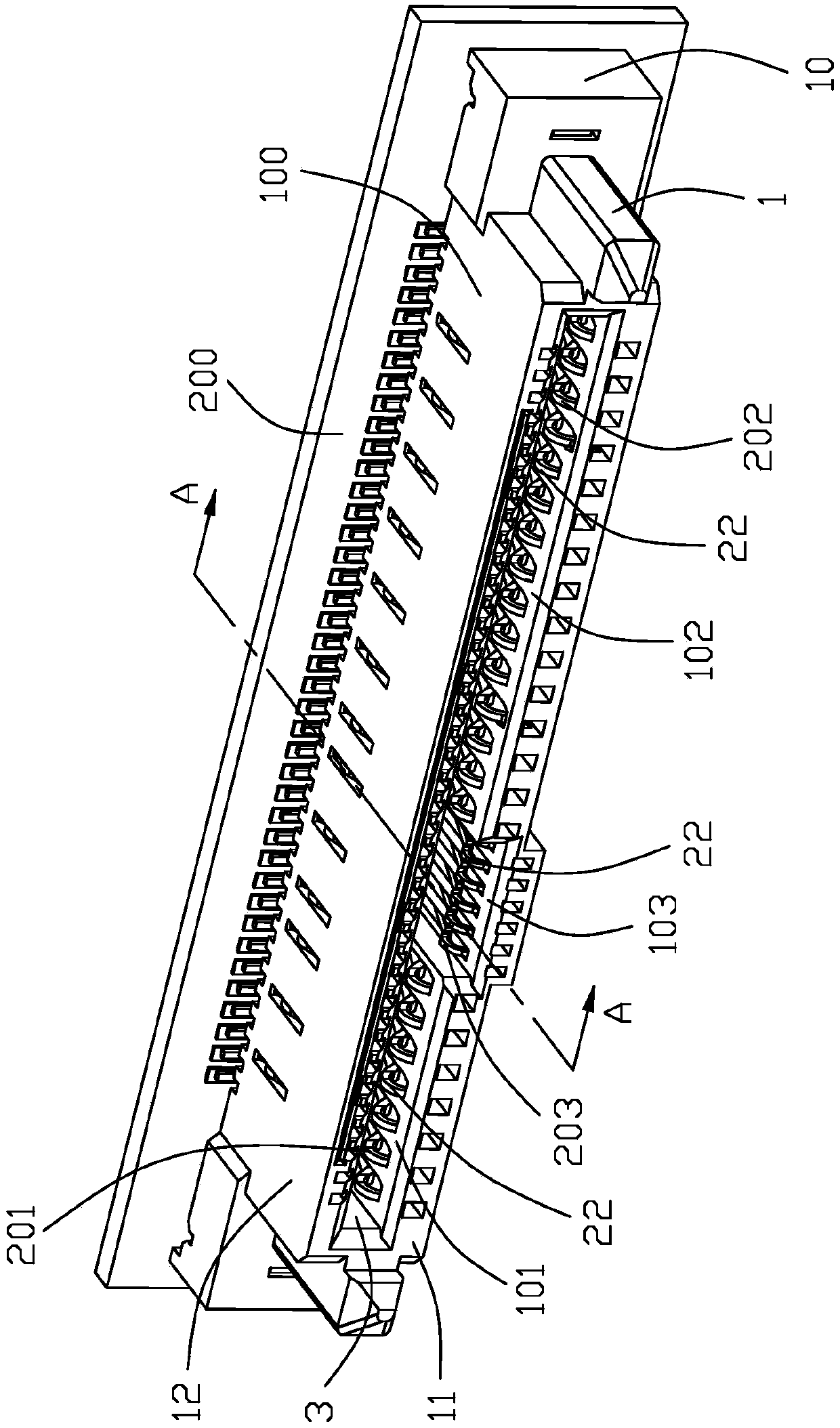
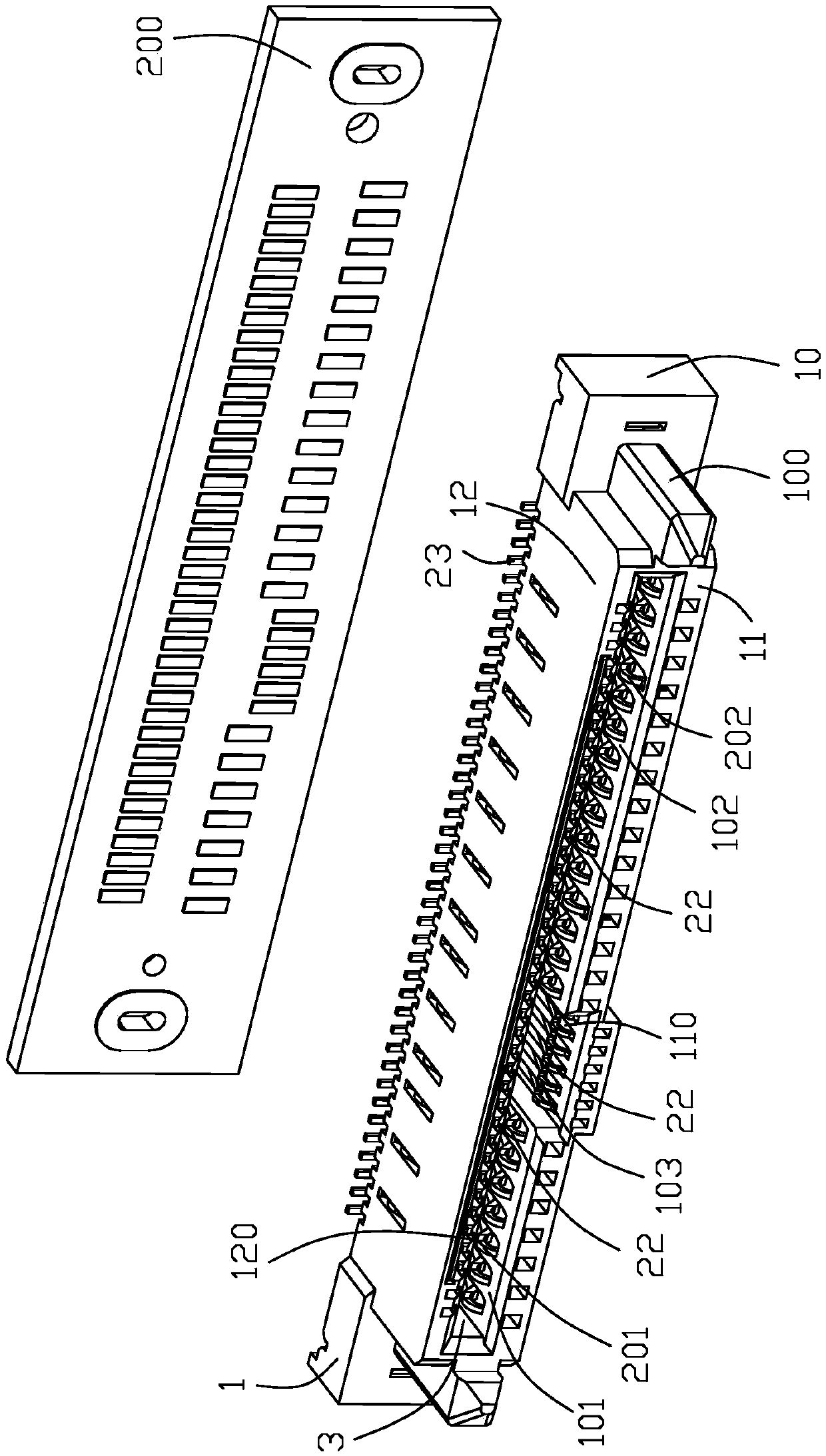
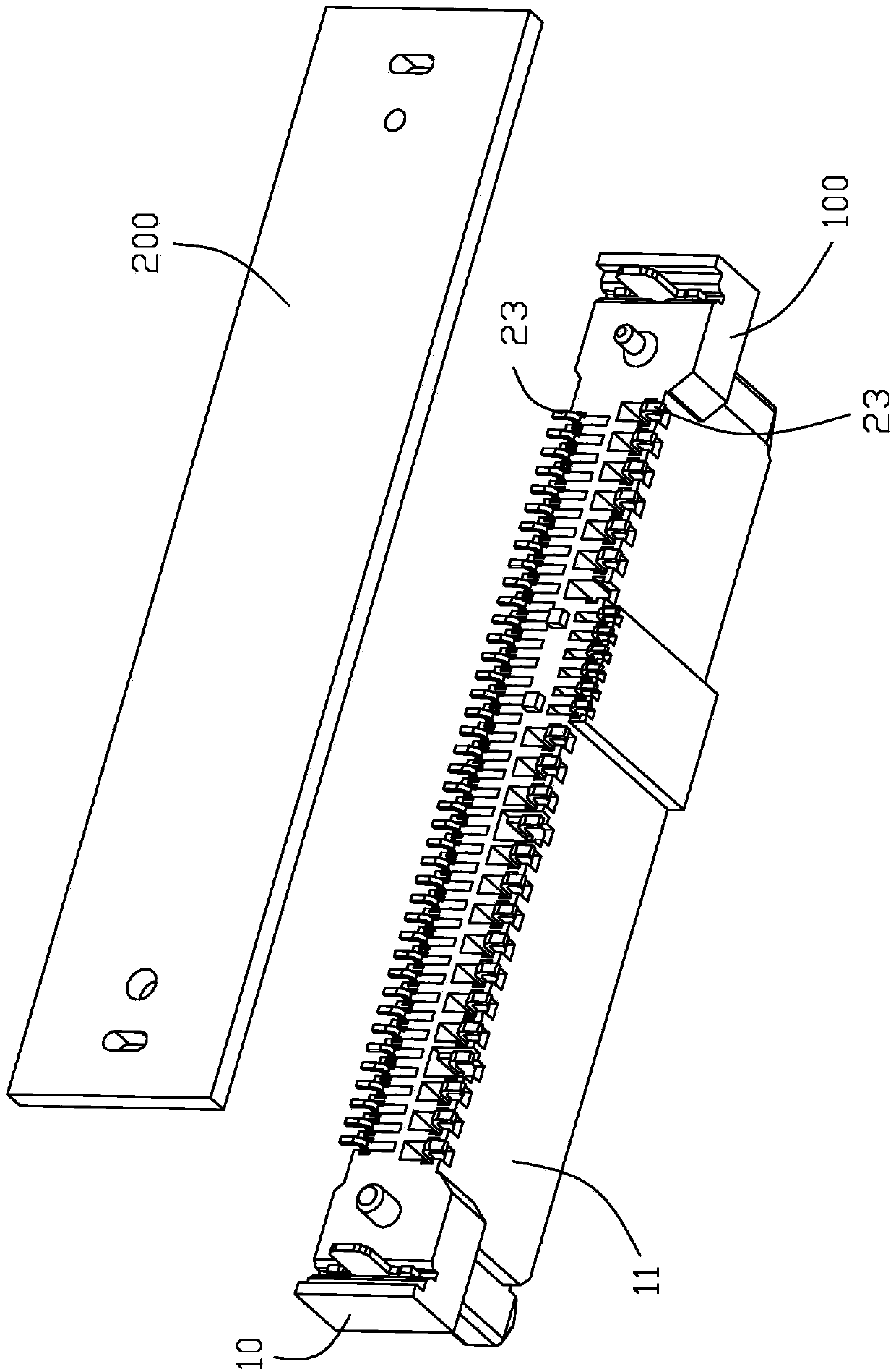
[0047] Below, will combine Figure 1 to Figure 9 The specific implementation manner of the conductive terminal of the present invention is introduced.

[0048] Such as Figure 1 to Figure 7 As shown, the present invention provides an electrical connector 100 for mounting on a circuit board 200 to transmit high-frequency signals, comprising a lengthwise insulating body 1 and a plurality of conductive terminals 2 held in the insulating body 1, the The insulating body 1 is provided with a continuous receiving groove 3 along its longitudinal direction, and the insulating body 1 includes a base 10, a first side wall 11 and a second side wall 12, and the first and second side walls 11, 12 Extended from the base 10 and located on opposite sides of the receiving groove 3 , the conductive terminal 2 is held on the first and second side walls 11 , 12 and includes a fixing portion fixed on the base 10 21. The arc-shaped bent contact portion 22 extending into the receiving groove 3 and ...


PUM


Abstract

The invention discloses an electric connector comprising an elongated insulating body and a plurality of conductive terminals fixed to the insulating body, wherein the insulating body is provided witha continuous receiving groove along a longitudinal direction thereof; the insulating body comprises a base portion, and first and second side walls which extend from the base portion and are locatedon the two opposite sides of the receiving groove; the conductive terminals are fixed to the first and second side walls and each includes a fixing portion fixed to the base portion and an arc-shapedbent contact portion extending into the receiving groove; and the width-to-thickness ratio of the contact portion of each conductive terminal is between 0.8 and 1.28. The impedance matching of the electric connector is improved, the differential signal transmission loss is reduced, and the high-frequency performance of the electric connector is improved.

Description

[0001] 【Technical field】 [0002] The invention relates to an electrical connector, in particular to a high-frequency electrical connector. [0003] 【Background technique】 [0004] With the improvement of the working speed of the digital circuit, the signal transmission rate of the high-frequency connector is getting higher and higher. With the increase of the data transmission rate, the rise time of the signal will be faster. When an impedance discontinuity is encountered on the conductive terminal of the circuit, there will be greater reflections. These reflections of the signal will change the shape of the signal, so the line impedance is a key factor affecting the integrity of the signal. For high-frequency connectors, it is very important to ensure the continuity of the impedance on the signal transmission path to achieve better impedance matching, so as to avoid large reflections of the signal. The high-frequency connector includes an insulating body and a differential s...

Claims


Application Information

Patent Timeline
Patent Type & Authority Applications(China)
IPC IPC(8): H01R13/6473H01R13/6474H01R13/02
CPCH01R13/6473H01R13/6474H01R13/02H01R12/714
Inventor 萧世伟萧裕三张衍智杨娜刘朦陈玉科
Owner FUDING PRECISION IND ZHENGZHOU CO LTD
Learn More