Simple constant-pressure fixture

A simple and simple technology for clamping, applied in clamping, manufacturing tools, supports, etc., can solve the problems of complicated fixture operation, inability to achieve rapid clamping, and inability to well adapt to the clamping needs of workpieces of different thicknesses, and achieve the structure of the fixture. Simple, suitable for mass production, avoids the effect of insufficient pressing force

Active Publication Date: 2019-07-05
NORTHEASTERN UNIV
View PDF8 Cites 1 Cited by
  • Summary
  • Abstract
  • Description
  • Claims
  • Application Information

AI Technical Summary

Problems solved by technology

[0004] The invention provides a simple constant pressure fixture, which aims to solve the problems existing in the prior art that the fixture is complicated to operate, unable to realize rapid clamping and unable to well adapt to the pressing requirements of workpieces with different thicknesses

Method used


Image

  • Simple constant-pressure fixture
  • Simple constant-pressure fixture
  • Simple constant-pressure fixture

Examples


Embodiment Construction

[0037] In order to better explain the present invention and facilitate understanding, the present invention will be described in detail below through specific embodiments in conjunction with the accompanying drawings.

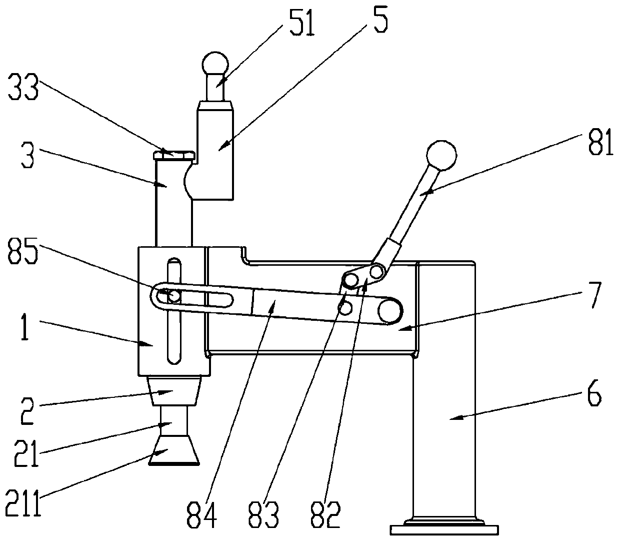
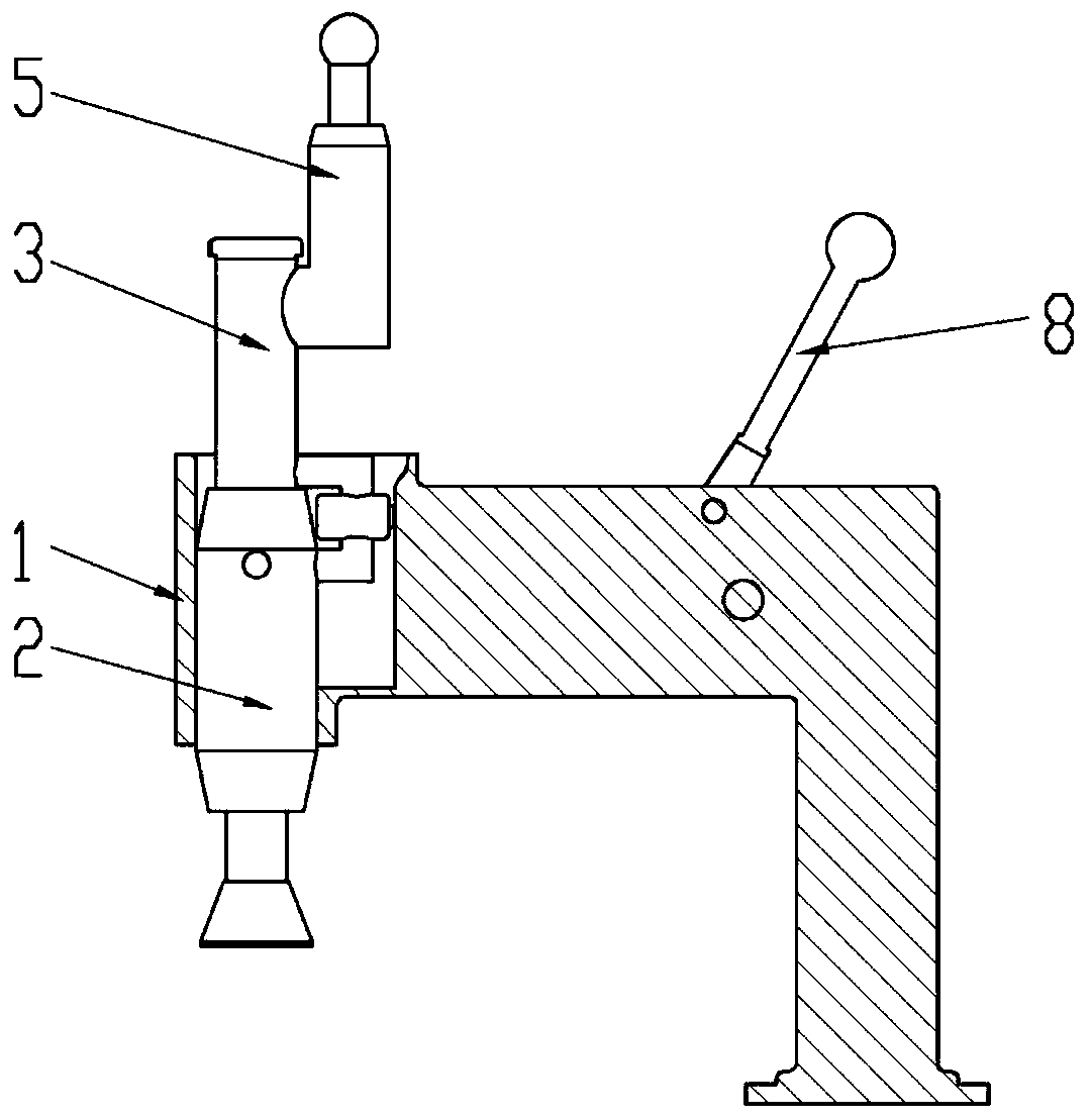
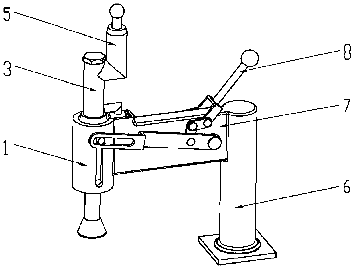
[0038] refer to Figure 1 to Figure 9 , the present application provides a simple constant pressure fixture, including a guide sleeve 1 , a pressing cylinder 2 and an upper cylinder 3 .

[0039] Wherein, the compression cylinder 2 is arranged in the guide sleeve 1 and can slide back and forth along the length direction of the guide sleeve 1. The compression cylinder 2 is provided with a compression piston 21. The cavity between them is filled with a liquid medium. The bottom end of the upper oil cylinder 3 is fixedly connected with the top end of the compression oil cylinder 2 and communicates with each other. A pressure limiting barrier 31 is placed at the place where the two communicate with each other. A pressure limiting spring 32 is arranged in the inner ...


PUM


Abstract

The invention relates to a simple constant-pressure fixture. The simple constant-pressure fixture comprises a guide sleeve, a hold-down oil cylinder and an upper oil cylinder; the hold-down oil cylinder is arranged in the guide sleeve; a hold-down piston is arranged in the hold-down oil cylinder; the bottom end of the upper oil cylinder is fixedly connected with the top end of the hold-down oil cylinder are fixedly connected, and the upper oil cylinder and the hold-down oil cylinder communicate with each other; a pressure limiting barrier part is arranged at the communicating position of the upper oil cylinder and the hold-down oil cylinder; a pressure limiting spring is arranged in the inner cavity of the upper oil cylinder; and a liquid return pipeline which can be selectively opened isfurther connected between the hold-down oil cylinder and the upper oil cylinder. The fixture disclosed by the invention is simple in structure and convenient to operate, is capable of meeting the requirement of having the same hold-down force on workpieces different in thickness, and avoids the defect that a simple hold-down device in the prior art has an excessive hold-down force on a thick workpiece but an insufficient hold-down force on a thin workpiece.

Description

technical field [0001] The invention belongs to the technical field of clamps, and in particular relates to a simple constant pressure clamp. Background technique [0002] When machining the workpiece material, it is usually necessary to use a fixture to fix the workpiece to prevent the plate-shaped workpiece from shaking during machining and affect the accuracy of machining. However, the design defects of the simple fixtures for fixing the workpiece in the prior art are more obvious. For example, the screw nut is used to tighten and clamp the workpiece, and the operation of the rotating screw is relatively cumbersome, which is not conducive to rapid clamping; It is well adapted to the rapid compression of workpieces of different thicknesses, and it is easy to cause the problem of excessive clamping force for thick workpieces and insufficient clamping force for thin workpieces. Therefore, in the face of large-scale workpiece processing, a simple and reliable fixture that ca...

Claims


Application Information

Patent Timeline
Patent Type & Authority Applications(China)
IPC IPC(8): B23Q3/08
CPCB23Q3/08B23Q3/082
Inventor 邵国庆兰亮云周伟
Owner NORTHEASTERN UNIV
Why Eureka
Try Eureka