
Non-contact optical component surface profile measuring device and method thereof

A technology for optical components and measuring devices, applied in the field of optical measurement, can solve the problems of lack of non-contact surface measuring devices, scratches on the surface of components, stray light affecting the optical system, etc., to achieve the effect of large-scale and high-precision measurement

Pending Publication Date: 2019-07-05
NANJING UNIV OF INFORMATION SCI & TECH
View PDF0 Cites 7 Cited by
  • Summary
  • Abstract
  • Description
  • Claims
  • Application Information

AI Technical Summary

Problems solved by technology

The contact method uses a mechanical probe to contact the surface of the part, and uses a grating ruler to measure the position of the probe to represent the surface height, but mechanical contact is likely to cause scratches on the surface of the component and affect the stray light of the optical system
Non-contact measurement is the development direction of component surface shape measurement technology. It has the advantages of high precision and no damage to the surface. However, it is different from the surface shape measurement of ordinary machinery and plastic parts. The surface of optical components is specular reflection, which is difficult for ordinary non-contact measurement methods. As a result, there is still a lack of a non-contact surface shape measurement device in the factory, and it is urgent to design a new measurement solution to solve the above problems

Method used


Image

  • Non-contact optical component surface profile measuring device and method thereof
  • Non-contact optical component surface profile measuring device and method thereof
  • Non-contact optical component surface profile measuring device and method thereof

Examples


Embodiment Construction

[0028] The present invention will now be described in further detail with reference to the accompanying drawings.

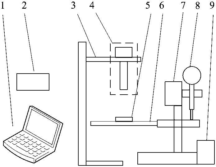
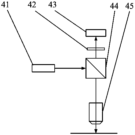
[0029] like figure 1 The non-contact optical element surface profile measurement device shown is used to measure the surface profile of flat surfaces and optical elements with large radius of curvature, including a host computer 1, an electronic control module 2, a probe support structure 3, an optical probe 4, and an element to be measured. 5. Component clamping device 6, Z-axis electric translation stage 7, dial indicator 8 and XY-axis electric translation stage 9 and other components. The optical probe 4 projects a focused light spot on the surface of the element, and the light spot is reflected back to the objective lens 45 to form a three-hole bright spot through the three-hole diaphragm 42 . Since the distance between the bright spots is related to the height position of the light spot, the surface thickness can be obtained by calculating the distance betw...


PUM


Abstract

The invention discloses a non-contact optical component surface profile measuring device and a method thereof. The device includes a host computer, an electronic control module, a probe supporting structure, an optical probe, a to-be-measured element, an element clamping device, a Z-axis electric translation stage, a dial indicator and an XY-axis electric translation stage; and the optical probe projects a focusing light spot on the surface of the to-be-measured element, and the light spot forms a three-hole bright spot through a three-hole diaphragm after being reflected back to an object lens. As the distance between the bright spots is related to the height position of the light spot, surface thicknesses can be obtained by collecting images in real time to calculate the distance betweenthe bright spots; in order to increase a height measuring range, the Z-axis electric translation stage can be used to move the to-be-measured element up and down, and the dial indicator can be used to measure the position of the element; and compared with traditional contact surface profile measuring systems, the device has the advantage of being non-contact, so that influences on the surface ofthe element can be avoided, and large measuring scope and high precision can be obtained.

Description

technical field [0001] The invention belongs to the field of optical measurement, in particular to a device and method for measuring the surface shape of a non-contact optical element. Background technique [0002] Optical components are widely used in daily life and various precision equipment, and their surface shape accuracy is a key factor affecting system performance. Design does not match. Therefore, high-precision optical components have strict requirements on the surface shape, and need to have good machining accuracy. Accurately measuring the lens surface shape during and after the processing is a key step to control the quality of the components. [0003] At present, the surface shape measurement methods of parts can be divided into two types: contact type and non-contact type. The contact method uses a mechanical probe to contact the surface of the part, and uses a grating ruler to measure the position of the probe to characterize the surface height, but mechani...

Claims


Application Information

Patent Timeline
Patent Type & Authority Applications(China)
IPC IPC(8): G01B11/00G01B11/25G01B5/20G01B5/004G01B11/03G01B11/06G01B5/06
CPCG01B11/002G01B11/2518G01B5/20G01B5/004G01B11/03G01B11/0608G01B5/061
Inventor 李潇潇张志恒张效宇曹杰君曹兆楼咸冯林
Owner NANJING UNIV OF INFORMATION SCI & TECH
Learn More