Another laser tracker geometric error compensation device

A laser tracker and compensation device technology, applied in the field of laser measurement, can solve the problem of no laser tracker geometric error, and achieve the effect of ensuring reliability and improving measurement accuracy

Active Publication Date: 2019-07-05
BEIJING UNIV OF TECH
View PDF10 Cites 6 Cited by
  • Summary
  • Abstract
  • Description
  • Claims
  • Application Information

AI Technical Summary

Problems solved by technology

However, there is currently no compensation device and compensation method for the geometric error of the laser tracker

Method used


Image

  • Another laser tracker geometric error compensation device
  • Another laser tracker geometric error compensation device
  • Another laser tracker geometric error compensation device

Examples


Embodiment Construction

[0019] The present invention will be further described in detail below in conjunction with the accompanying drawings and specific embodiments. However, it should not be understood that the scope of the above subject matter of the present invention is limited to the following implementation manners, and all technologies realized based on the contents of the present invention belong to the scope of the present invention.

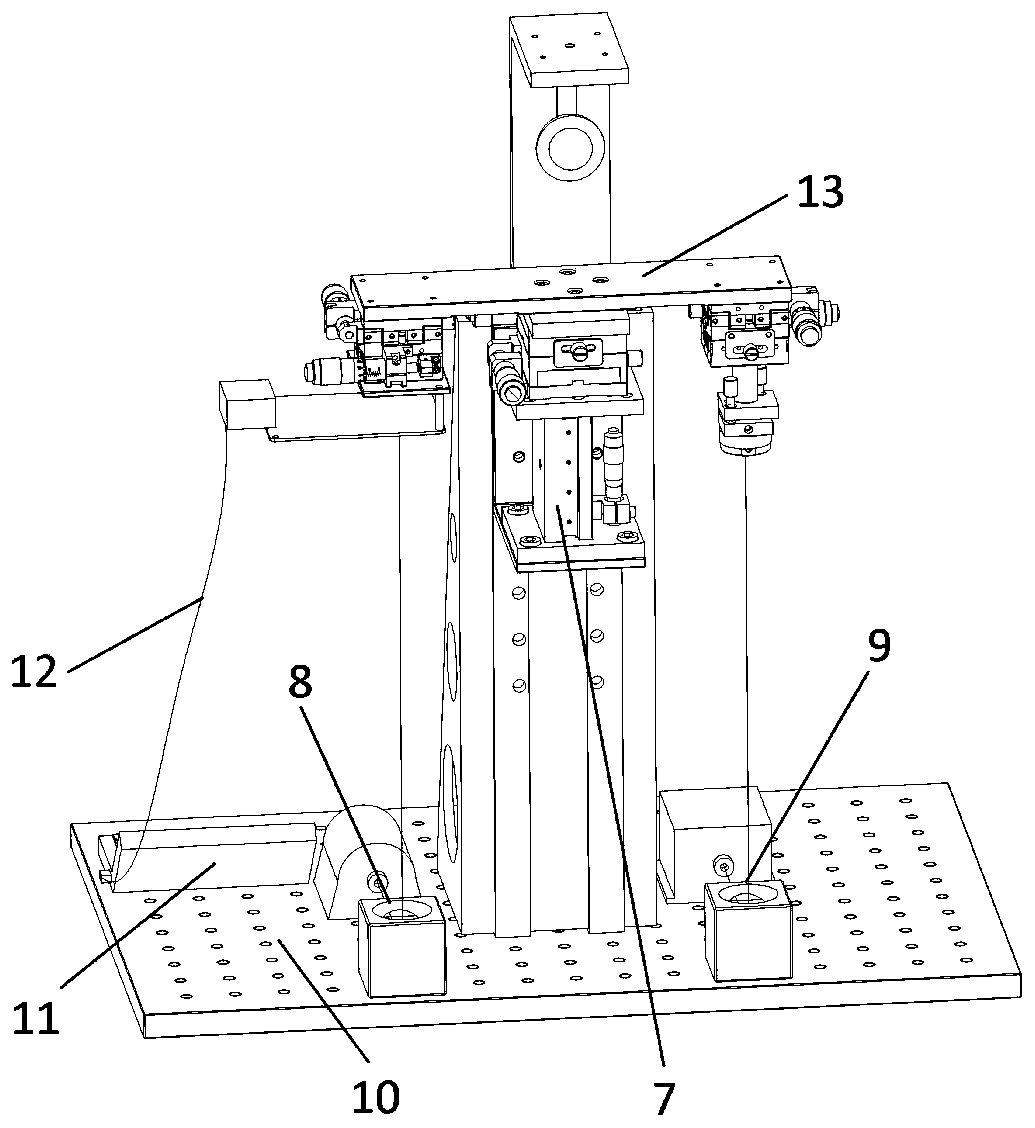
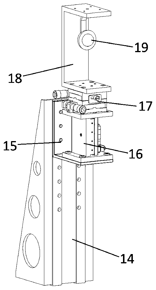
[0020] like figure 2 and image 3 As shown, the steel frame 14 is installed on the positioning hole plate 10 by screw connection, and the L-shaped connecting frame 15 is installed on the steel frame 14 by screw connection. The vertical slide table 16 is installed on the L-shaped connecting frame 15 by threaded connection. The first manual two-dimensional slide table 17 is installed on the upper end of the vertical slide table 16 through a threaded connection. The U-shaped connecting frame 18 is installed on the upper end of the first manual two-dimensional...


PUM


Abstract

The invention discloses another laser tracker geometric error compensation device. The compensation device is divided into two parts, namely a cat-eye vertical movement structure and a laser tracker rotation structure. The cat-eye vertical movement structure is divided into three parts, namely a column guide rail structure, a laser collimation structure and a positioning error compensation structure. The laser tracker rotation structure is composed of a laser tracker, an electric two-dimensional platform and a precise rotary table. Through the compensation device, a system measurement error caused by a geometric error can be subject to effective compensation, the measurement precision of the laser tracker is improved, and meanwhile the reliability of a laser tracking measurement system based on a polygonal method is guaranteed.

Description

technical field [0001] The invention relates to the field of laser measurement, in particular to a geometric error compensation device for a laser tracker. Background technique [0002] Laser tracker is a high-precision large-scale measuring instrument in the field of industrial measurement. It has the characteristics of large measurement space, high measurement efficiency, high measurement accuracy, and simple operation. It is similar to a portable three-coordinate measuring machine and is widely used in shipbuilding, automobile manufacturing, and aircraft manufacturing. The laser tracker is a measurement system based on the principle of multilateral method, which is specially used for calibrating high-end CNC equipment such as three-coordinate measuring machines and CNC machine tools. Although the multilateral method is the method with the highest theoretical accuracy among various methods for calibrating CNC equipment using laser tracking measurement systems, it also req...

Claims


Application Information

Patent Timeline
Patent Type & Authority Applications(China)
IPC IPC(8): G01B11/00
CPCG01B11/002
Inventor 石照耀宋辉旭陈洪芳
Owner BEIJING UNIV OF TECH
Why Eureka
Try Eureka