
Chip testing system

A chip testing, chip technology, applied in the direction of electronic circuit testing, measuring electricity, measuring devices, etc., can solve the problems of poor airflow, incomplete heat dissipation of temperature-controlled heat dissipation equipment, slow heat dissipation, etc., to achieve smooth airflow, rapid and thorough heat dissipation , to facilitate the effect of rapid cooling

Active Publication Date: 2019-07-05
GIGADEVICE SEMICON (BEIJING) INC +1
View PDF6 Cites 2 Cited by
  • Summary
  • Abstract
  • Description
  • Claims
  • Application Information

AI Technical Summary

Problems solved by technology

[0004] In view of the above problems, the purpose of the embodiments of the present invention is to provide a chip testing system to solve the problems of incomplete heat dissipation, unsmooth airflow and slow heat dissipation in existing temperature-controlled heat dissipation equipment.

Method used


Image

  • Chip testing system
  • Chip testing system
  • Chip testing system

Examples


Embodiment Construction

[0020] In order to make the above objects, features and advantages of the present invention more comprehensible, the present invention will be further described in detail below in conjunction with the accompanying drawings and specific embodiments.

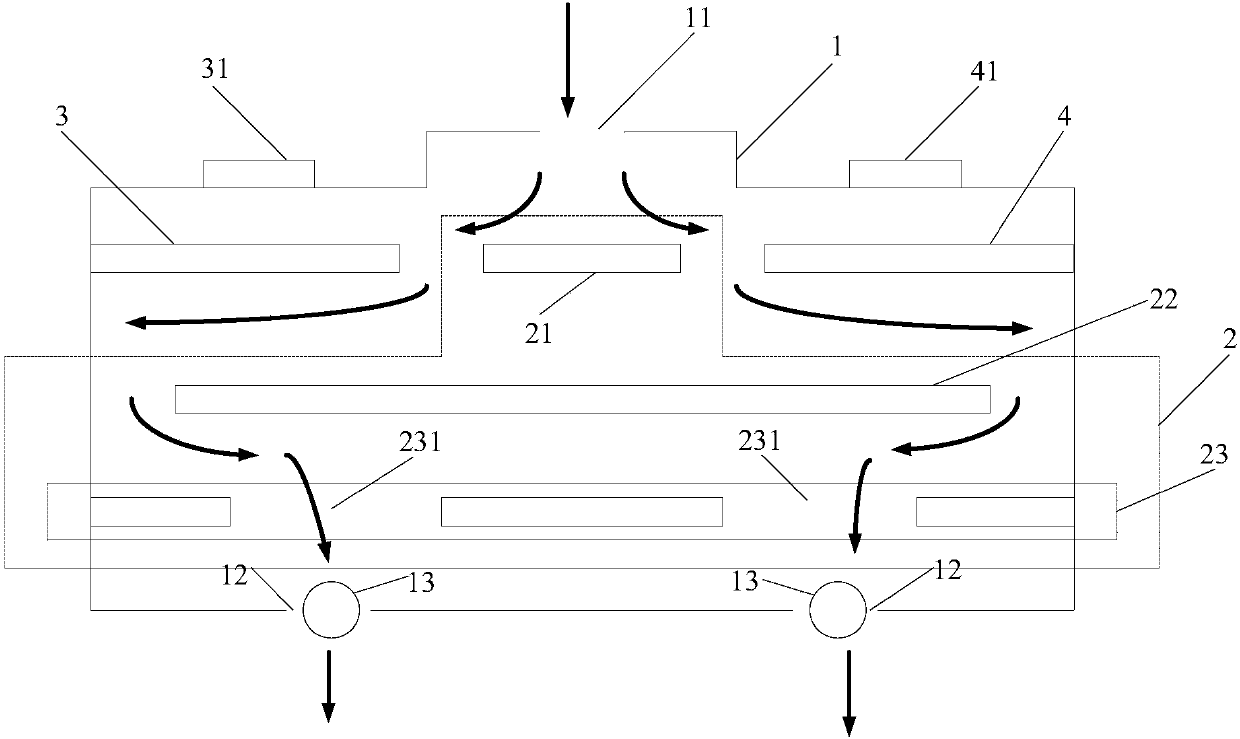
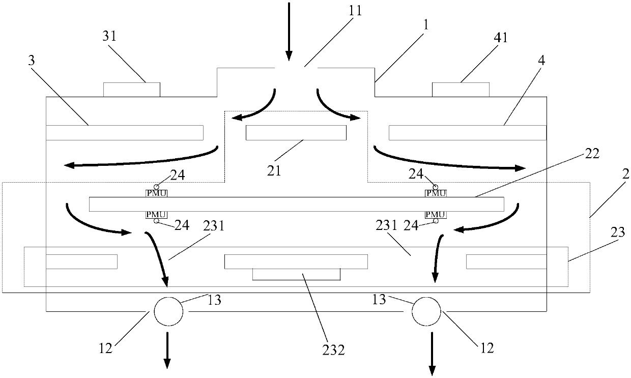
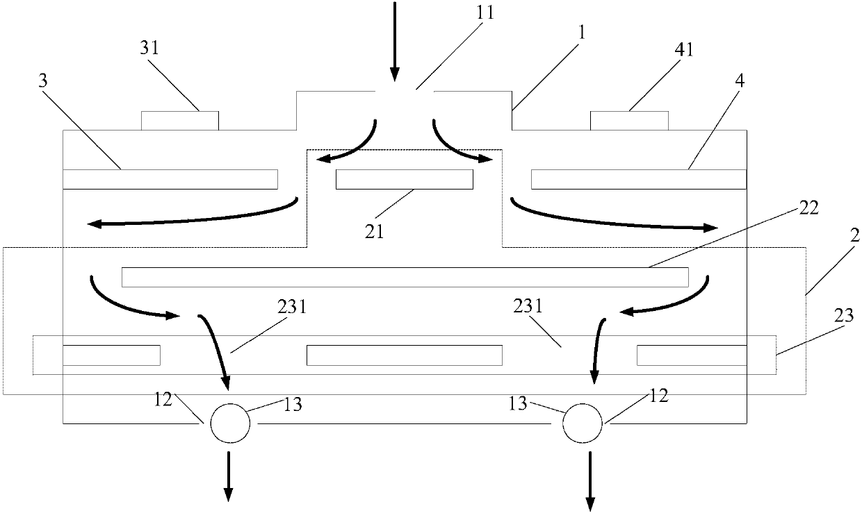
[0021] refer to figure 1 , which shows a structural block diagram of an embodiment of a chip testing system of the present invention, which may specifically include a heat dissipation chassis 1, a chip testing device 2 disposed in the heat dissipation chassis 1, a first chip interface board 3 and a second chip interface board 4. The chip testing device 2 includes a main control board 21, a measurement unit board 22 and a power supply board 23, an air inlet 11 is arranged on the top of the heat dissipation chassis 1, and at least one air outlet 12 is arranged on the bottom of the heat dissipation chassis 1 together with at least one air outlet 12. A corresponding at least one fan 13, the first chip interface board 3, the second chi...


PUM


Abstract

The invention provides a chip testing system. The chip testing system comprises a heat dissipation cabinet as well as a chip testing device, a first chip interface board and a second chip interface board which are arranged in the heat dissipation cabinet; the chip testing device comprises a main control board, a measuring unit board and a power source board; an air inlet is formed in the top of the cabinet; at least one air outlet and at least one fan are arranged at the bottom of the cabinet; the first chip interface plate, the second chip interface board and the main control board are arranged above the measuring unit board; the power source board is arranged below the measuring unit board; the first chip interface board and the second chip interface board are arranged at two sides of the main control board respectively; gaps are formed between the first chip interface board and the second chip interface board and the main control board; no gaps are left between the first chip interface board and the second chip interface board and the side wall of the heat dissipation cabinet; chip insertion grooves in the first chip interface board and the second chip interface board are arranged outside the cabinet; gaps are formed between two sides of the measuring unit board and the side wall of the cabinet; no gaps exist between the power source board and the side wall of the heat dissipation cabinet; and the power source board comprises at least one through hole. The air circulation performance of the cabinet is good, the environment temperature of the equipment can be controlled,and high-temperature protection can be provided for the equipment.

Description

technical field [0001] The invention relates to the technical field of chip testing, in particular to a chip testing system. Background technique [0002] With the continuous development of electronic equipment, the heat dissipation of the equipment caused by the thermal effect of electronic components has attracted much attention. Excessively high ambient temperature will lead to the increase of the deviation of the measurement unit in the test equipment and the rapid aging of the components in the test equipment, and even lead to The test equipment is damaged. Therefore, most test equipment (especially chip test equipment) will be equipped with temperature-controlled heat dissipation equipment. In order to ensure the accuracy of test results, reasonable temperature-controlled heat dissipation equipment is particularly important. [0003] Most of the existing temperature control and heat dissipation equipment is air-cooled equipment. The air-cooled equipment uses the fluid...

Claims


Application Information

Patent Timeline
Patent Type & Authority Applications(China)
IPC IPC(8): G01R31/28H05K7/20
CPCG01R31/2851H05K7/20145
Inventor 靳家奇蔡德智王永成宋飞凡韩飞
Owner GIGADEVICE SEMICON (BEIJING) INC
Learn More