Method for solving effective characteristic line of non-rotary tool through discrete workpiece curved surface

A non-rotation, feature line technology, applied in computer parts, special data processing applications, instruments, etc., can solve the problem that the error distribution of tool and workpiece design surface is difficult to accurately solve.

Pending Publication Date: 2019-07-05
SHANDONG UNIV OF TECH +1
View PDF7 Cites 0 Cited by
  • Summary
  • Abstract
  • Description
  • Claims
  • Application Information

AI Technical Summary

Problems solved by technology

[0005] The purpose of the present invention is to propose a method for solving the effective characteristic line of a non-rotating tool through discrete workpiece curved surfaces, and solve the problem that the error distribution between the tool and the workpiece design surface is difficult to accurately solve when the non-rotating tool is CNC machining complex curved surfaces. Rotary tool attitude optimization provides important calculation basis

Method used


Image

  • Method for solving effective characteristic line of non-rotary tool through discrete workpiece curved surface
  • Method for solving effective characteristic line of non-rotary tool through discrete workpiece curved surface
  • Method for solving effective characteristic line of non-rotary tool through discrete workpiece curved surface

Examples


Embodiment Construction

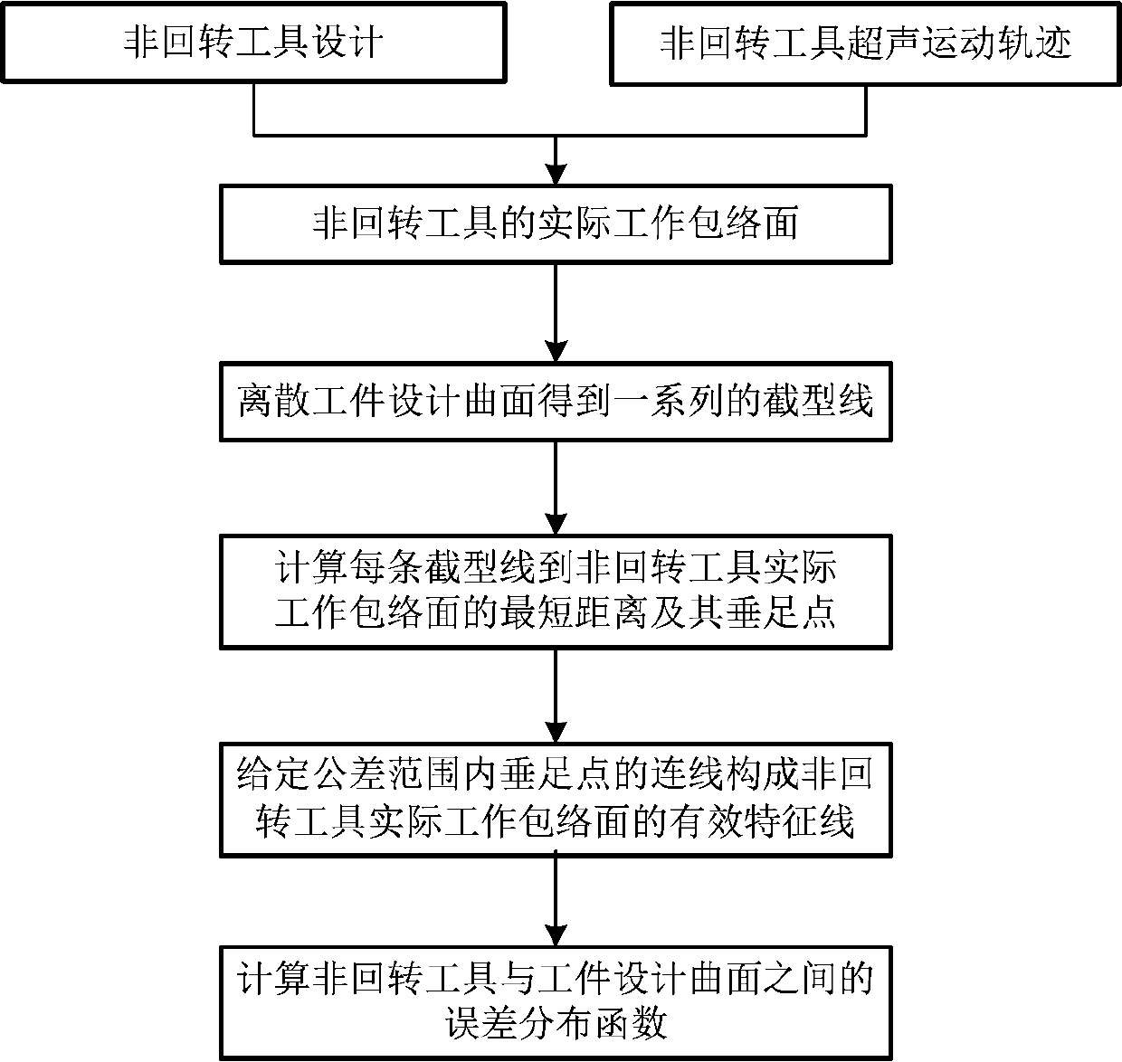
[0022] A method of the present invention for solving the effective characteristic line of a non-rotating tool through a discrete workpiece surface, the basic flow is as follows figure 1 As shown, its preferred specific implementation method includes:

[0023] Step A, according to the geometric shape of the non-rotating tool and the relative motion relationship of the tool, the actual working envelope surface of the non-rotating tool is solved by using the longitude / latitude method and the traditional envelope theory. Described step A specifically is:

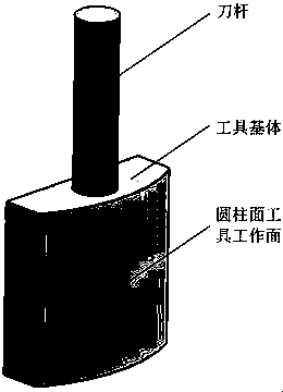
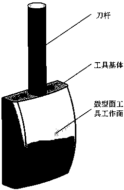
[0024] (1) The design of non-rotating tools is analyzed according to the geometric shape of the workpiece design surface (such as ruled surface, free-form surface, etc.). If the workpiece design surface is a ruled surface, you can choose a non-rotating tool with a cylindrical surface, such as figure 2 shown; if the workpiece design surface is a free-form surface, you can choose a non-rotating tool with a drum surface, such as ...


PUM


Abstract

The invention discloses a method for solving an effective characteristic line of a non-rotating tool through a discrete workpiece curved surface, which comprises the following steps of: solving an actual working enveloping surface of the non-rotating tool by utilizing a warp / weft method and a traditional enveloping theory according to a geometrical shape of the non-rotating tool and a relative motion relation of the non-rotating tool; dispersing the designed curved surface of the workpiece at the bottom of the non-rotary tool into a series of section lines according to the feeding direction ofthe non-rotary tool; respectively calculating the shortest distance between each section line and the actual working envelope surface of the non-rotary tool and the vertical foot point of the sectionline by utilizing the shortest distance line pair principle and a numerical iteration algorithm, and forming an effective characteristic line between the actual working envelope surface of the non-rotary tool and the machined surface of the workpiece by connecting lines of all the vertical foot points in a given tolerance range; respectively solving the shortest distances from the vertical foot points on the effective characteristic lines to the workpiece design curved surface, obtaining a series of vertical foot points and shortest distance line segments on the workpiece design curved surface, and forming an error distribution function of the non-rotary tool and the workpiece design curved surface by the set of all the shortest distance line segments. According to the method, the error distribution condition of the non-rotary tool during machining of the complex curved surface can be accurately solved, an important calculation basis is provided for attitude optimization of the non-rotary tool, and a certain practical application value is achieved.

Description

technical field [0001] The invention relates to a multi-axis numerical control machining programming method, in particular to a method for solving the effective characteristic line of a non-rotating tool through a discrete workpiece surface, and belongs to the field of numerical control machining. Background technique [0002] The processing of semi-closed surfaces has become a very important bottleneck in the field of mechanical processing. Closed impellers, impellers and turbine guide vanes are all in semi-enclosed and curved spaces, which are very prone to interference when machining with straight-shank rotary tools. Even if the rotary tool can be used to mill, grind and polish it from both sides of the flow channel, it is necessary to choose a tool with a small diameter to avoid collisions, resulting in insufficient tool rigidity, low processing efficiency, and poor processing accuracy. And other issues. The use of non-rotating tools (such as vibration polishing tools)...

Claims


Application Information

Patent Timeline
IPC IPC(8): G06K9/62G06F17/50
CPCG06F30/20G06F18/2413G06F18/245
Inventor 徐汝锋李勋陈志同程祥郑光明
Owner SHANDONG UNIV OF TECH
Why Eureka
Try Eureka