User-side energy equipment intelligent maintenance method

A technology on the user side and equipment, applied in the direction of data processing applications, instruments, character and pattern recognition, etc., can solve the problems of reducing the competitive advantage of operation and maintenance providers, high professional requirements for operation and maintenance personnel, and low user stickiness, so as to reduce system Operation and maintenance costs and equipment failure risks, and the effect of improving energy supply quality and reliability

Active Publication Date: 2019-07-05
北京快电科技有限公司
View PDF4 Cites 24 Cited by
  • Summary
  • Abstract
  • Description
  • Claims
  • Application Information

AI Technical Summary

Problems solved by technology

[0009] 1. The cost of manpower occupation is very high, and most of the work needs to be done by manpower;
[0010] 2. The work efficiency is low. Generally, there are two people and one car for inspection and maintenance, and the inspection and maintenance is carried out within the designated range. In addition, there are time spent on the road and communication time, so the work efficiency is relatively low;
The current training mode is basically lectures and mentoring, because the possibility of accidents is relatively low, personnel are less likely to simulate faults, and there is no real-time online monitoring of equipment, so we can only rely on emergency repairs after accidents to learn from them; 1 ) There are many types of energy equipment, which requires high professionalism of operation and maintenance personnel; 2) The operating conditions of energy equipment are harsh, and it is difficult for personnel to approach and observe under the operating state; 3) There are many operating data of energy equipment, and the existing operation and maintenance personnel have ...

Method used


Image

  • User-side energy equipment intelligent maintenance method
  • User-side energy equipment intelligent maintenance method
  • User-side energy equipment intelligent maintenance method

Examples


Embodiment Construction

[0038] It should be noted that, in the case of no conflict, the following technical solutions and technical features can be combined with each other.

[0039] The specific embodiment of the present invention will be further described below in conjunction with accompanying drawing:

[0040] Such as Figure 1-3 As shown, a smart maintenance method for user-side energy equipment is applicable to building energy systems, where the building energy system includes multiple energy equipment; the above method includes:

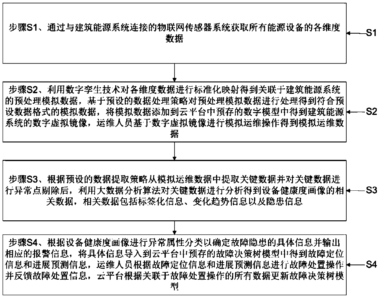
[0041] Step S1. Obtain data of various dimensions of all the above-mentioned energy equipment through the Internet of Things sensor system connected to the above-mentioned building energy system;

[0042] Step S2. Using digital twin technology to perform standardized mapping on the above-mentioned dimensional data to obtain the pre-processed simulation data associated with the above-mentioned building energy system, and process the above-mentioned pre-processed simul...


PUM


Abstract

The invention provides a user-side energy equipment intelligent maintenance method. The method comprises the following steps of obtaining the all-dimensional data of all energy equipment through an Internet of Things sensor system; adding the analog data into a digital model pre-stored in a cloud platform to obtain a digital virtual mirror image of the building energy system, and performing analogoperation and maintenance operation by operation and maintenance personnel based on the digital virtual mirror image to obtain the analog operation and maintenance data; extracting the key data fromthe simulated operation and maintenance data, carrying out abnormal point elimination on the key data, and analyzing the key data by utilizing a big data analysis algorithm to obtain relevant data ofthe equipment health degree portrait; carrying out the abnormal attribute classification according to the equipment health degree portrait to determine specific information of the fault hidden dangerand output corresponding alarm information, and using the cloud platform to update the fault decision tree model according to all data associated with the fault handling operation. The method has thebeneficial effects that the operation and maintenance cost is reduced, and the operation and maintenance efficiency is improved.

Description

technical field [0001] The invention relates to the technical field of building energy management, in particular to a smart maintenance method for user-side energy equipment using digital twins and abnormal big data analysis. Background technique [0002] At present, the energy provided to users is mainly divided into two categories: one is separate power supply, heat supply, and gas supply, and the other is emerging multi-energy comprehensive supply, such as combined cooling, heating and power supply, integration of source, network and load, and combined cooling and heating supply. Wait, these all need maintenance. Electricity, as the core energy species for mutual coordination between various energy sources, is the most important means of energy transmission, adjustment, and complementarity. Therefore, from the perspective of intelligent operation and maintenance of power distribution, the overview of existing technologies has the following aspects. [0003] Operation: Co...

Claims


Application Information

Patent Timeline
IPC IPC(8): G06K9/62G06Q10/00G06Q10/04G06Q50/06
CPCG06Q10/20G06Q10/04G06Q50/06G06F18/23G06F18/2135G06F18/2433G06F18/24
Inventor 彭海波田海亭杨阳
Owner 北京快电科技有限公司
Why Eureka
Try Eureka