Cooler for heat dissipation of transformer

A technology of transformers and coolers, which is applied to the cooling of transformers/inductors, components of transformers/inductors, electrical components, etc., can solve the problems of poor cooling effect, poor cooling effect, affecting the normal operation of transformers, etc., and achieve good cooling effect. Effect

Active Publication Date: 2019-07-05
马鞍山电力规划勘察设计院有限责任公司
View PDF2 Cites 7 Cited by
  • Summary
  • Abstract
  • Description
  • Claims
  • Application Information

AI Technical Summary

Problems solved by technology

[0003] Transformers generally work for a long time, and the temperature of the transformer has a great influence on the operation of the transformer. If the temperature is too high, it will affect the normal operation of the transformer; a device that can cool the transformer is urgently needed
[0004] The Chinese literature is CN108777216A, which is a cooling and cooling device for transformers. The invention uses water cooling and air cooling to double cool the transformer, improve the cooling effect, ensure the stable operation of the transformer, and prevent the normal operation of the transformer from being too high. ;By controlling the water temperature in the water tank, the cooling effect of the water cooling is improved; and the transformer is dissipated through the heat sink to improve the cooling effect, but the device cannot cool the cooling liquid, so the cooling effect is poor
[0005] The Chinese literature is CN208045253U’s power transformer water cooling device. The utility model uses an external cooling water tank to cool the oil in the transformer cooling oil tank, and uses a temperature sensor to measure the temperature of the cooling water, feedback the cooling water temperature in time, and control the speed of the circulating water of the water pump. It can effectively cool the transformer indirectly, but it is only water-cooled, and the cooling effect is poor

Method used


Image

  • Cooler for heat dissipation of transformer
  • Cooler for heat dissipation of transformer
  • Cooler for heat dissipation of transformer

Examples


Embodiment Construction

[0030] The technical solutions in the embodiments of the present invention will be clearly and completely described below in conjunction with the accompanying drawings in the embodiments of the present invention. Obviously, the described embodiments are only part of the embodiments of the present invention, not all of them. Based on the embodiments of the present invention, other embodiments obtained by persons of ordinary skill in the art without making creative efforts all belong to the protection scope of the present invention.

[0031] see Figure 1-5 , the present invention provides a technical solution:

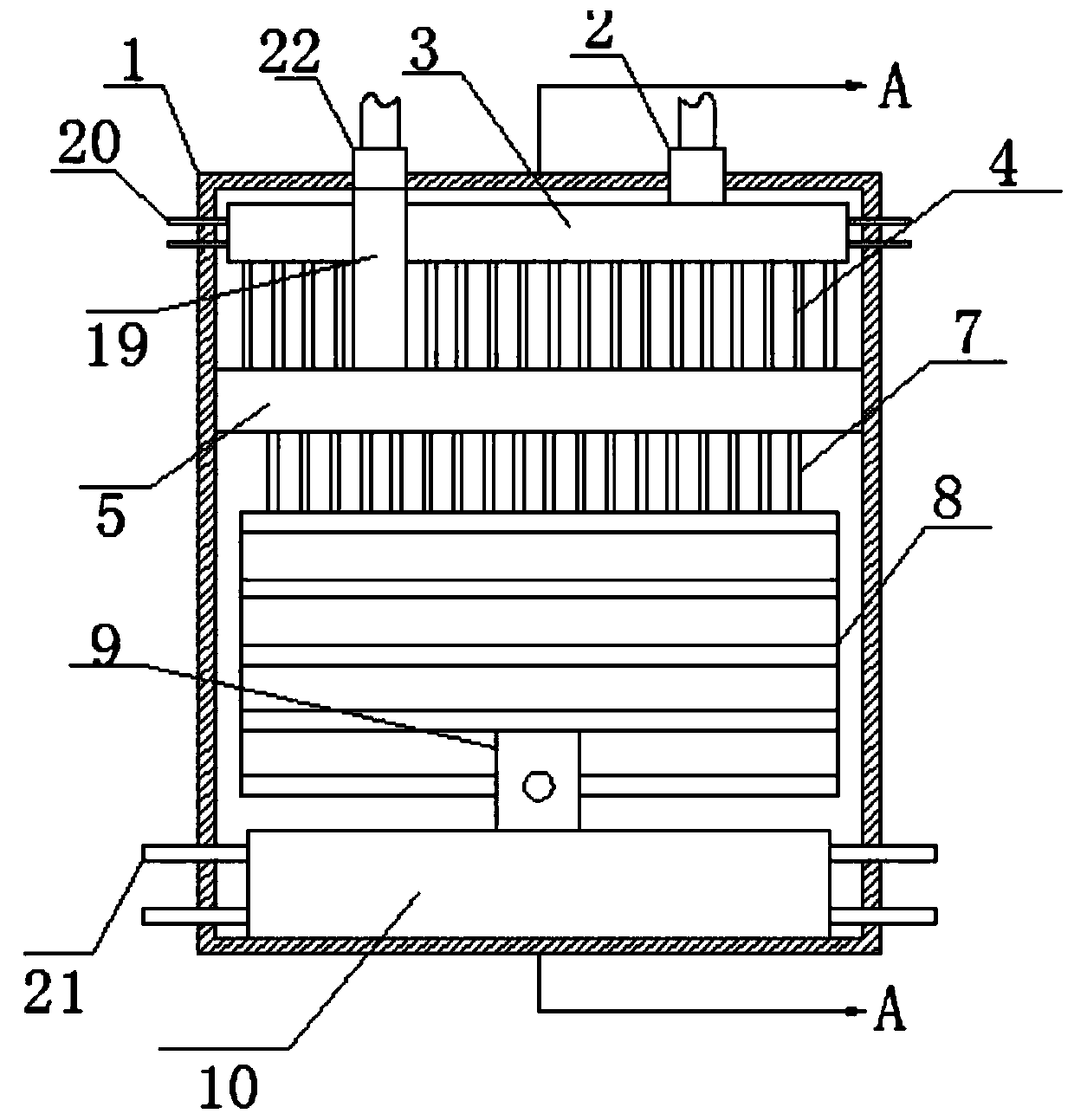
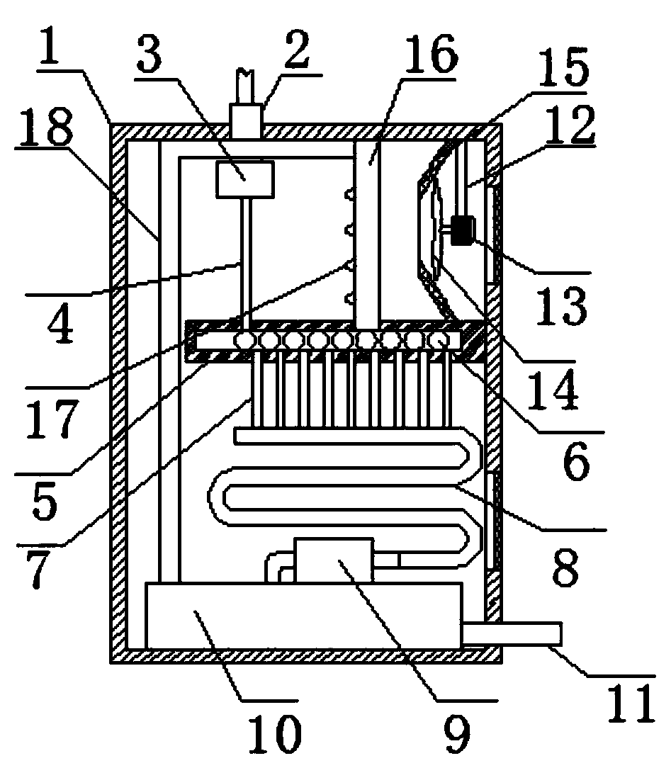
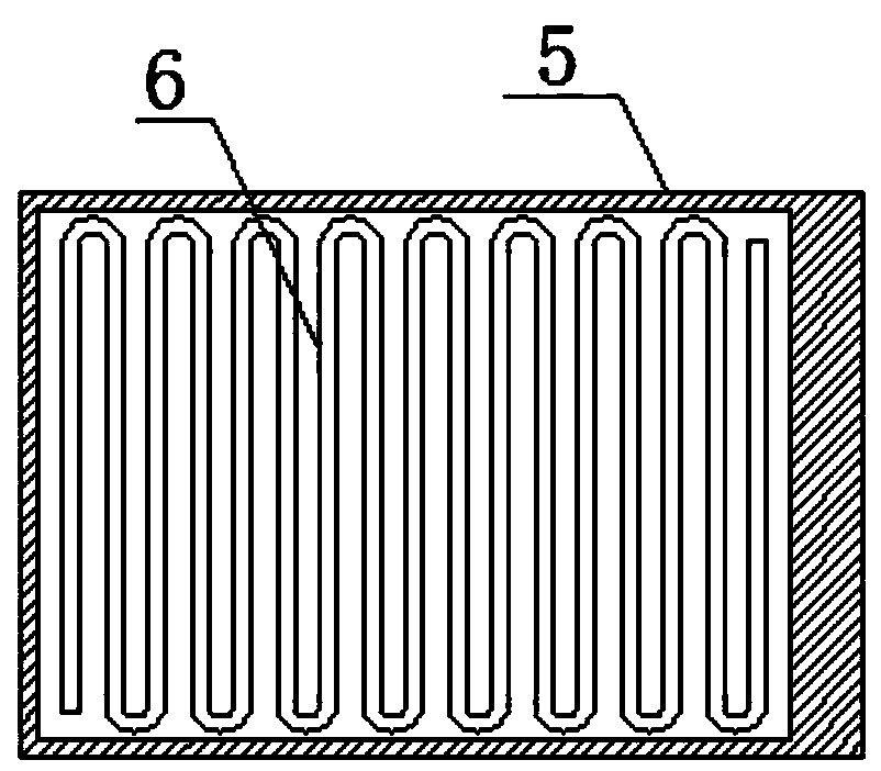
[0032] A cooler for transformer heat dissipation, comprising a box 1, an oil inlet pipe 2 and a heat dissipation pipe 3, the box 1 is fixedly connected to the side wall of a transformer body 23, the oil inlet pipe 2 is connected through the upper end of the box 1, and the oil inlet pipe 2 is located in the box 1 One end inside is connected through the radiating pipe 3;...


PUM


Abstract

The invention discloses a cooler for heat dissipation of a transformer. The cooler comprises a box, an oil inlet pipe and a heat dissipation pipe, the box is fixedly connected to the side wall of a transformer body, the oil inlet pipe is in through connection to the upper end of the box, and the end, located in the box, of the oil inlet pipe is in through connection to the heat dissipation pipe. Amotor rotates to drive fan blades to rotate, to lead the outside air into the box such that a first slim tube is cooled, at the same time, the wind from the fan comes out from air outlet heads through a wind outlet plate and the airflow goes out from the air outlet heads such that the temperature of the airflow is lowered and the temperature of the airflow blown to the first slim tube is low, andliquid coolant in the air outlet plate cools the incoming airflow again, so that a good cooling effect is achieved.

Description

technical field [0001] The invention relates to the technical field of transformer equipment, in particular to a cooler for transformer heat dissipation. Background technique [0002] A transformer is a device that transforms AC voltage, current, and impedance. When an AC current passes through the primary coil, an AC magnetic flux is generated in the iron core (or magnetic core), which induces a voltage (or current) in the secondary coil. The transformer consists of an iron core (or magnetic core) and a coil. The coil has two or more windings. The winding connected to the power supply is called the primary coil, and the remaining windings are called the secondary coil. A transformer is a device that uses electromagnetic mutual induction to transform voltage, current and impedance. There are many types of transformers, which can be divided into distribution transformers, power transformers, fully sealed transformers, combined transformers, dry-type transformers, rapid cooli...

Claims


Application Information

Patent Timeline
IPC IPC(8): H01F27/08H01F27/10H01F27/12H01F27/16H01F27/22
CPCH01F27/085H01F27/10H01F27/12H01F27/16H01F27/22
Inventor 戴荣玉徐林赵启翠
Owner 马鞍山电力规划勘察设计院有限责任公司
Why Eureka
Try Eureka