Ejector unit and fuel cell hydrogen circulation system having same

A fuel cell stack and ejector technology, which is applied to fuel cells, fuel cell additives, circuits, etc., can solve the problem of insufficient ejection of the ejector, and achieve the needs of improving the hydrogen circulation capacity and reducing the hydrogen pressure. The effect of improving the utilization rate of hydrogen

Pending Publication Date: 2019-07-05
上海楞次新能源汽车科技有限公司
View PDF0 Cites 4 Cited by
  • Summary
  • Abstract
  • Description
  • Claims
  • Application Information

AI Technical Summary

Problems solved by technology

[0007] In view of the above problems, the object of the present invention is to provide an ejector unit and a fuel cell hydrogen circulation system equipped with the ejector unit, which can solve the problem of insufficient injection volume of the ejector at low flow rates, and at the same time reduce the Reduce the demand for hydrogen pressure at the front of the ejector, thereby improving hydrogen utilization, system efficiency and economy

Method used


Image

  • Ejector unit and fuel cell hydrogen circulation system having same
  • Ejector unit and fuel cell hydrogen circulation system having same
  • Ejector unit and fuel cell hydrogen circulation system having same

Examples


Embodiment 1)

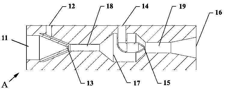
[0078] figure 1 is a sectional view of the ejector unit A according to Embodiment 1 of the present invention. Such as figure 1 As shown, the first ejector 6 and the second ejector 5 are connected in series in a coaxial form, and the first jet hole 13 and the second jet hole 15 are also located at the series axis of the ejector unit A , so that the ejector unit A is formed in the form of a center-to-center jet. Therefore, at the axial center position, the first jet inlet 11, the first jet hole 13 communicating with the first jet inlet 11, the first mixing hole 13 communicating with the first jet hole 13 and the first drainage inlet 12 are sequentially formed. Space 18, the first outlet 17 communicating with the first mixing space 18 and having the function of the second drainage inlet, the second jet hole 15 communicating with the second jet inlet 14, and the second jet hole 15 and the first outlet 17 at the same time The communicating second mixing space 19 and the second o...

Embodiment 2)

[0080] figure 2 is a sectional view of an ejector unit B according to Embodiment 2 of the present invention. Such as figure 2 As shown, the first ejector 6 and the second ejector 5 are connected in series in a coaxial form, and the first jet hole 13 is located at the center of the serial axis of the ejector unit A, while the second jet hole 15 The ejector unit B is formed in a ring form on the inner side wall portion of the ejector unit B so that the ejector unit B is formed in the form of a center-annular jet. On the series axis of the first ejector 6 and the second ejector 5, a first jet inlet 11, a first jet hole 13 communicating with the first jet inlet 11, a first jet hole 13 and a first jet hole 13 are formed in sequence. A first mixing space 18 that communicates with the first flow inlet 12 at the same time, a first outlet 17 that communicates with the first mixing space 18 and also functions as a second flow inlet, and a second outlet 17 that communicates with the ...

Embodiment 3)

[0082] image 3 is a sectional view of an ejector unit C according to Embodiment 3 of the present invention. Such as image 3As shown, the first ejector 6 and the second ejector 5 are connected in series in a coaxial form, and the first jet hole 13 and the second jet hole 15 are formed in the inner side of the ejector unit C in a ring form. The wall, and thus the ejector unit C, is formed in the form of an annular-annular jet. On the series axis of the first ejector 6 and the second ejector 5, there are sequentially formed a first drainage inlet 12, a first mixing space 18 communicating with the first jet hole 13 and directly communicating with the first drainage inlet 12 , the first outlet 17 communicating with the first mixing space 18 and having the function of the second drainage inlet, the second mixing space 19 communicating with the second jet hole 15 and directly communicating with the first outlet 17, and the second mixing space 19 The connected second outlet 16, w...


PUM


Abstract

The present invention provides an ejector unit and a fuel cell hydrogen circulation system having the same, wherein the ejector unit comprises a first ejector and a second ejector connected in series,the first ejector comprises: a first jet flow inlet, a first drainage inlet, a first jet flow hole communicating with the first jet flow inlet, a first mixing space communicating with the first drainage inlet and the first jet flow hole, and a first outlet communicating with the first mixing space; the second ejector includes: a second jet flow inlet, a second drainage inlet communicating with the first outlet, a second jet flow hole communicating with the second jet flow inlet, a second mixing space communicating with the second drainage inlet and the second jet flow hole, and a second outlet communicating with the second mixing space; the structure that the first jet flow inlet is connected with the second jet flow inlet in parallel and the first drainage inlet is connected with the second drainage inlet in series is formed. According to the ejector unit and the fuel cell hydrogen circulation system of the invention, flexible and various ejection combinations can be realized to meetthe requirements of hydrogen circulation volume under different power conditions.

Description

technical field [0001] The invention relates to the technical field of fuel cells, in particular to a vehicle fuel cell engine system, in particular to an ejector unit and a fuel cell hydrogen circulation system equipped with the ejector unit. Background technique [0002] At present, the commonly used fuel cell is a power generation device that directly converts the chemical energy of the fuel into electrical energy. The fuel cell system has high energy conversion efficiency and is an ideal energy utilization method. There is a broad development prospect for commercial applications. important research significance. [0003] In practice, in order to avoid problems such as power generation performance degradation caused by too low reaction gas concentration and water flooding caused by reduced gas flow, the supply of hydrogen and oxygen in the fuel cell must be higher than the amount consumed by the electrochemical reaction. In order to improve the utilization rate of hydrog...

Claims


Application Information

Patent Timeline
Patent Type & Authority Applications(China)
IPC IPC(8): H01M8/04089H01M8/0438H01M8/04746
CPCH01M8/04097H01M8/04104H01M8/04201H01M8/04388H01M8/04753Y02E60/50
Inventor 马天才杜玮祖文强刘通朱东
Owner 上海楞次新能源汽车科技有限公司
Why Eureka
Try Eureka