Stable horizontal fuel gas generator and gas generating process thereof

A gas generator, horizontal technology, applied in the direction of combustion method, liquid fuel supply/distribution, etc., can solve the problems of low gas production efficiency, large blowing power, different degree of oil mixing, etc., to reduce energy consumption and reduce pressure Demand, full effect of bubble splitting

Active Publication Date: 2017-05-17
SHANDONG UNIV OF TECH +1
View PDF11 Cites 0 Cited by
  • Summary
  • Abstract
  • Description
  • Claims
  • Application Information

AI Technical Summary

Problems solved by technology

As a result, the overall volume of the gas generating tank is large, takes up a large space, consumes a lot of blowing power, and the final gas production efficiency is low
Moreover, with the production process, the liquid level of the oil in the gas generation tank will change, the depth of the air blown will also change, and the pressure when the bubbles are generated will also change, so the size of the burst bubbles is also different, and then it is different from the oil. The degree of mixing is also different, which eventually leads to unstable quality of the obtained light hydrocarbon gas

Method used


Image

  • Stable horizontal fuel gas generator and gas generating process thereof
  • Stable horizontal fuel gas generator and gas generating process thereof
  • Stable horizontal fuel gas generator and gas generating process thereof

Examples


Embodiment 1

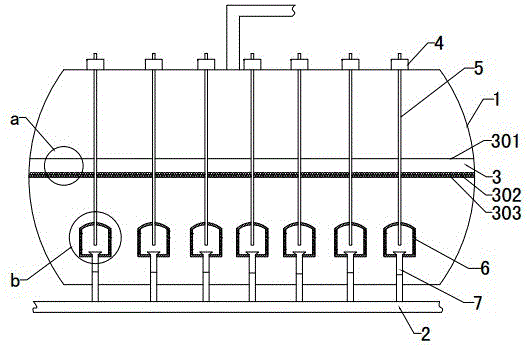
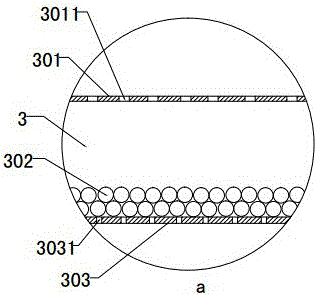
[0024] The upper partition 301 and the lower partition 303 of the bubble adjustment plate 3 are set at an interval of 12cm; the aperture of the upper mesh 3011 offered on the upper partition 301 is 1.0cm, and the aperture of the lower mesh 3031 offered on the lower partition 303 is 0.5cm ; The air bubble adjustment plate 3 is filled with activated carbon balls 302 accounting for 20% of its volume, and the diameter of the activated carbon balls 302 is 1.4 cm ~ 1.6 cm;

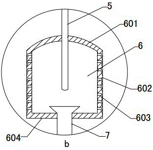
[0025] Bubbler 6 blows air bubbles at 0.46m below the oil surface during operation, and the air bubbles rise to the air bubble adjustment plate 3 and enter the air bubble adjustment plate 3 through the mesh. Extruded and collided, the air bubbles that reach the upper surface of the air bubble adjustment plate 3 escape from the mesh, rise above the oil surface and collect, and are output by the gas outlet pipe, and the gas output by the gas pipeline burns stably.

Embodiment 2

[0027] The upper partition 301 and the lower partition 303 of the air bubble adjustment plate 3 are set at an interval of 10cm; the aperture of the upper mesh 3011 offered on the upper partition 301 is 0.9cm, and the aperture of the lower mesh 3031 offered on the lower partition 303 is 0.44cm ; The air bubble adjustment plate 3 is filled with activated carbon balls 302 accounting for 20% of its volume, and the diameter of the activated carbon balls 302 is 1.4 cm ~ 1.6 cm;

[0028]Bubbler 6 blows out air bubbles 0.44m below the oil surface during operation, and the air bubbles rise to the air bubble adjustment plate 3, and enter the air bubble adjustment plate 3 through the mesh, and the incoming air bubbles drive the activated carbon balls 302 to make irregular movements and constantly interact with each other. Extruded and collided, the air bubbles that reach the upper surface of the air bubble adjustment plate 3 escape from the mesh, rise above the oil surface and collect, an...

Embodiment 3

[0030] The upper partition 301 and the lower partition 303 of the bubble adjustment plate 3 are set at an interval of 8cm; the aperture of the upper mesh 3011 offered on the upper partition 301 is 0.8 cm, and the aperture of the lower mesh 3031 offered on the lower partition 303 is 0.4 cm ; The air bubble adjustment plate 3 is filled with activated carbon balls 302 accounting for 18% to 22% of its volume, and the diameter of the activated carbon balls 302 is 1.4 cm to 1.6 cm;

[0031] Bubbler 6 blows out air bubbles 0.5m below the oil surface during operation, and the air bubbles rise to the air bubble adjustment plate 3, enter the air bubble adjustment plate 3 through the mesh, and the entered air bubbles drive the activated carbon balls 302 to make irregular movements and constantly interact with each other. Extruded and collided, the air bubbles that reach the upper surface of the air bubble adjustment plate 3 escape from the mesh, rise above the oil surface and collect, and...


PUM


Abstract

The invention relates to a stable horizontal fuel gas generator and a gas generating process thereof and belongs to the technical field of fuel gas generation equipment. The stable horizontal fuel gas generator is characterized in that an air bubble adjusting plate (3) is arranged in the middle of a tank body, meshes are formed in upper and lower plate surfaces of the air bubble adjusting plate (3), and the air bubble adjusting plate (3) is filled with active carbon balls (302) which account for 18-22% of the volume of the air bubble adjusting plate (3); a plurality of bubblers (6) in the tank body (1) are arranged below the air bubble adjusting plate (3) through a lifting mechanism; and the bubblers (6) and an air inlet pipe (2) are connected through telescopic air inlet branch pipes. During gas generation, the bubblers bubble 0.4-0.5m below the oil level. Air and a fuel material are fully contacted and mixed in a relatively shallow liquid level, so that the pressure demand is reduced, and meanwhile, the depths of the bubbles are determined, so that the gas generating quality is stable.

Description

technical field [0001] A stable horizontal gas generator and its gas production process belong to the technical field of gas generating equipment. Background technique [0002] The light hydrocarbon gas generation system is a technology that uses petrochemical by-products and the residual liquid of liquefied petroleum gas as raw materials, and produces fuel gas through special equipment, which can realize the full utilization of existing energy. The existing fuel gas generating device is basically a bubbling type, that is, air is blown into the gas generating tank, and the gas bubbles are naturally moved in the oil and mixed with light hydrocarbons to form combustible light hydrocarbon gas. In this way, in order to fully mix the air with the light hydrocarbons in the oil, the air needs to be blown into a certain depth. In this way, the oil storage depth in the spherical gas generating tank is large, and a relatively high pressure is required to blow the air in. As a result,...

Claims


Application Information

Patent Timeline
Patent Type & Authority Applications(China)
IPC IPC(8): F23K5/22
CPCF23K5/22
Inventor 巴奉丽万隆巴奉军王玮彭庆梁
Owner SHANDONG UNIV OF TECH
Why Eureka
Try Eureka