X-Y-axis antenna base and antenna system

An antenna base, X-Y technology, applied to antennas, folded antennas, antenna parts and other directions, can solve the problems of difficult to achieve rapid antenna adjustment, assembly, transportation and locking, inconvenient installation and transportation, large moment of inertia, etc., to achieve simple servo control. Reliable, low assembly difficulty, and the effect of reducing the moment of inertia

Inactive Publication Date: 2019-07-05
CHINA ELECTRONIC TECH GRP CORP NO 38 RES INST
View PDF6 Cites 3 Cited by
  • Summary
  • Abstract
  • Description
  • Claims
  • Application Information

AI Technical Summary

Problems solved by technology

[0004] The traditional X-Y antenna pedestal requires two-axis rotation of the antenna pedestal and multiple feeds to achieve overhead tracking. Therefore, in order to ensure high reliability of overhead tracking, the structure of the existing X-Y antenna pedestal is generally large in size, Heavy weight, large moment of inertia, high cost, very inconvenient installation and transportation, difficult to achieve tasks such as quick adjustment, assembly, transportation, and locking of the antenna

Method used


Image

  • X-Y-axis antenna base and antenna system
  • X-Y-axis antenna base and antenna system
  • X-Y-axis antenna base and antenna system

Examples


Embodiment 1

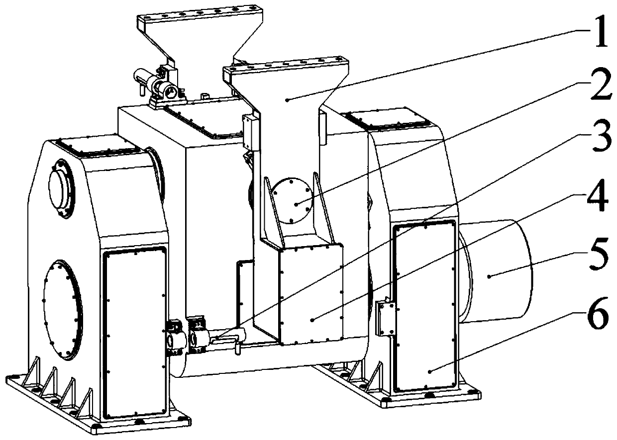
[0030] like figure 1 as shown, figure 1 It is the overall structural diagram of the X-Y antenna base of the present invention; the X-Y antenna base of the present invention includes an X-axis mechanism 5 and a Y-axis mechanism 2, and the X-axis mechanism 5 and the Y-axis mechanism 2 are fixedly connected, so The Y-axis mechanism 2 is fixedly provided with a support arm 1, and the X-Y antenna base is connected with the antenna mechanism through the support arm 1; the X-axis mechanism 5 includes an X-axis 19 and a first braking module; the Y-axis The mechanism 2 includes a Y-axis 7 and a second braking module, and the X-axis 19 and the Y-axis 7 are arranged orthogonally and coplanarly. The first brake module controls the rotation state of the X-axis 19; the second brake module controls the rotation state of the Y-axis 7; the X-axis 19 is fixedly connected to the Y-axis mechanism 2, and the The X-axis 19 can drive the Y-axis mechanism 2 to rotate, and the Y-axis 7 can drive the...

Embodiment 2

[0035] The X-Y antenna base includes the support arm 1 , the Y-axis mechanism 2 , the counterweight 4 , the X-axis mechanism 5 , and a base 6 .

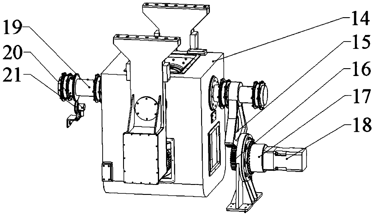
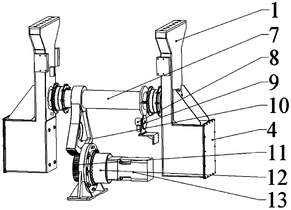
[0036] like figure 2 , image 3 , Figure 4 as shown, figure 2 is a structural view of the X-axis mechanism 5; image 3 is a structural view of the Y-axis mechanism 2; Figure 4It is a positional view of the X-axis 19 and the Y-axis 7; the first braking module includes a first rotating gear 15, a first driving gear 16, a first speed reducer 17, a first motor 18, a first double A piece gear 20, a first encoder 21; the second braking module includes a turntable 14, a second double-piece gear 9, a second rotating gear 10, a second drive gear 11, a second speed reducer 12, and a second motor 13 , the second encoder 8 .

[0037] The base 6 is symmetrically arranged on both sides of the Y-axis mechanism 2, and the first rotating gear 15, the first driving gear 16, the first reducer 17, and the first motor 18 are all arranged In th...

Embodiment 3

[0048] like Figure 5 as shown, Figure 5 It is the overall structural diagram of the antenna system of the present invention; the antenna system of the present invention includes the X-Y antenna seat and the antenna mechanism 22, and the antenna mechanism 22 is fixedly arranged on the support arm 1, and through the X-Y The control of the type antenna base realizes the directional movement of the antenna mechanism 22.

[0049] like Figure 6 as shown, Figure 6 It is a moving view of the antenna mechanism; the antenna mechanism 22 includes a central array block 23 and a pair of side array blocks 24 symmetrically arranged on the central array block 23, the central array block 23 and the The support arm 1 is fixedly connected, and the two side array blocks 24 are connected to the middle array block 23 through a turning mechanism, and the turning mechanism can realize the folding and unfolding of the antenna mechanism 22 .

[0050] like Figure 7 and Figure 8 as shown, F...


PUM


Abstract

The invention discloses an X-Y-axis antenna base and an antenna system. The X-Y-axis antenna base comprises an X-axis mechanism and a Y-axis mechanism which are fixedly connected. A support arm is fixedly disposed on the Y-axis mechanism. An X-Y-type antenna base is connected to an antenna mechanism through the support arm. The X-axis mechanism includes an X-axis and a first brake module. The Y-axis mechanism includes a Y-axis and a second brake module. The X-axis and the Y-axis are orthogonally coplanar. The first brake module controls the rotation state of the X-axis. The second brake modulecontrols the rotation state of the Y-axis. The X-axis and the Y-axis mechanism are fixedly connected to each other. The X-axis can drive the Y-axis mechanism to rotate. The Y-axis can drive the support arm to rotate. The X-axis and the Y-axis are orthogonally coplanar so as to reduce the overall volume of the X-Y-type antenna base, achieve compact structure, facilitate the transportation of the X-Y-type antenna base, and effectively reduce the moment of inertia.

Description

technical field [0001] The invention relates to the technical field of radar antennas, in particular to an X-Y axis antenna base and an antenna system. Background technique [0002] The overhead tracking of the antenna pedestal is a technical means for real-time and continuous tracking of satellites. It is mainly used in polar-orbiting satellites, inclined-orbit synchronous satellites, and "communication in motion" equipment. [0003] At present, the widely used antenna base mechanism forms are mainly pitch and azimuth antenna bases and X-Y antenna bases. For the pitch and azimuth antenna base, due to the blind cone area in the operation process, it cannot effectively achieve overhead tracking, which is limited in practicability; the X-Y type antenna base is set at X because its blind cone area is not at the top. Below the axis, it avoids the disadvantages of using the pitch and azimuth antenna base, and can meet the requirements of overhead tracking of the antenna. [000...

Claims


Application Information

Patent Timeline
Patent Type & Authority Applications(China)
IPC IPC(8): H01Q1/12H01Q3/08H01Q1/08
CPCH01Q1/08H01Q1/1235H01Q3/08
Inventor 王虎肖海红芮振华王耀华方旭
Owner CHINA ELECTRONIC TECH GRP CORP NO 38 RES INST
Why Eureka
Try Eureka