
Shunt harmonic control circuit

A harmonic control and harmonic suppression technology, which is applied to electrical components, amplifiers, improved amplifiers to improve efficiency, etc., can solve the problems that the circuit design cannot be simple and efficient, it is difficult to ensure high-order harmonics, and limit efficiency

Pending Publication Date: 2019-07-05
HANGZHOU DIANZI UNIV FUYANG ELECTRONIC INFORMATION RES INST CO LTD
View PDF7 Cites 0 Cited by
  • Summary
  • Abstract
  • Description
  • Claims
  • Application Information

AI Technical Summary

Problems solved by technology

However, in this traditional harmonic circuit method, each harmonic control module needs to be controlled at the same time at the impedance level, which is bound to affect each other, and the circuit design cannot be simple and efficient, and it is difficult to ensure that each high-order harmonic can be controlled to a certain extent. Ideal state, limiting efficiency gains

Method used


Image

  • Shunt harmonic control circuit
  • Shunt harmonic control circuit
  • Shunt harmonic control circuit

Examples


Embodiment Construction

[0075] The following are specific embodiments of the present invention, which further elaborate on this solution. However, the present invention is not limited to these examples.

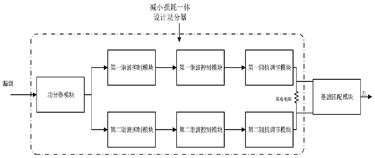
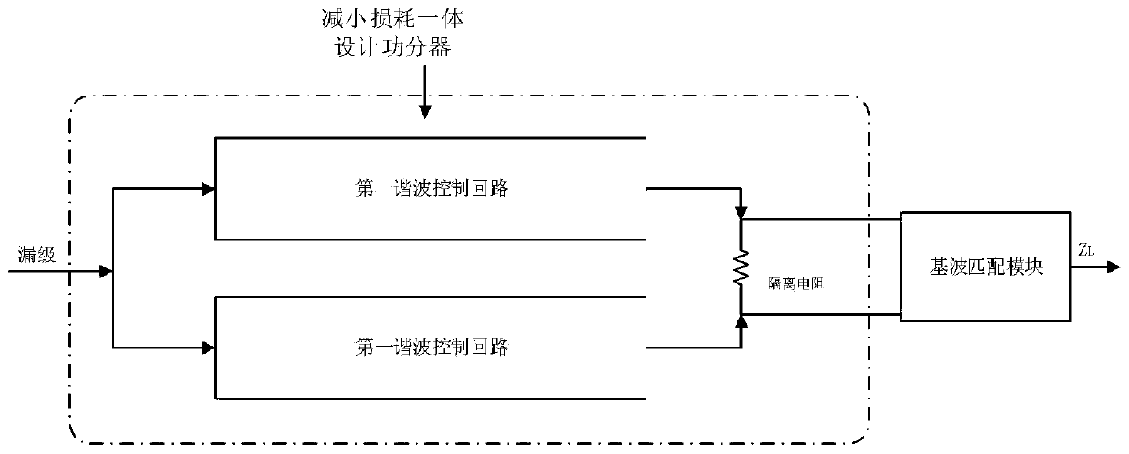
[0076] see figure 2 , shows a functional block diagram of a shunt harmonic control circuit of the present invention, including a power divider module, a first harmonic control loop, a second harmonic control loop and a fundamental wave matching module, wherein,

[0077] The power divider module is connected to the output terminal of the power amplifier, and is used to divide the power signal into two outputs;

[0078] An isolation resistor is set between the first harmonic control loop and the second harmonic control loop;

[0079] The first harmonic control loop is connected to an output end of the power divider module, and at least a first harmonic suppression module, a first harmonic control module and a first impedance adjustment module are provided, and the first harmonic The suppression mo...


PUM


Abstract

The invention discloses a shunt harmonic control circuit, which comprises a power divider module, a first harmonic control loop, a second harmonic control loop and a fundamental wave matching module;the power divider module is connected with the output end of a power amplifier and is used for dividing a power signal into two paths and outputting the two paths; the first harmonic control loop is connected with one output end of the power divider module and is at least provided with a first harmonic suppression module, a first harmonic control module and a first impedance adjusting module, andthe first harmonic suppression module is used for retaining third harmonic and filtering out other harmonic waves; the first harmonic control module is used for controlling third harmonics; and the first impedance adjusting module is used for carrying out impedance adjustment on the second harmonic control loop and outputting the power signal to the fundamental wave matching module. By adopting the technical scheme of the invention, the difference between the circuit and the voltage waveform and the ideal value can be reduced, so that the power amplification efficiency is improved.

Description

technical field [0001] The invention belongs to the technical field of harmonic control matching, and relates to a branch harmonic control circuit, which is used for matching transistor drain impedance to load impedance (output matching network) and improving the efficiency of a power amplifier. Background technique [0002] With the continuous development of 5G technology, the requirements for power amplification technology are getting higher and higher. It is necessary to ensure that the design is small in size and its working performance is guaranteed. Therefore, if the power amplifier wants to improve the performance of the device while maintaining a small size, it is undoubtedly necessary to improve its own efficiency. To improve the efficiency of the power amplifier, it is necessary to design an excellent harmonic control matching circuit, so how to design an excellent power amplifier matching circuit has become a research hotspot. [0003] For the common power amplif...

Claims


Application Information

Patent Timeline
Patent Type & Authority Applications(China)
IPC IPC(8): H03F1/02H03F1/56H03F3/21
CPCH03F1/0211H03F1/56H03F3/21
Inventor 刘国华郭灿天赐程知群周国祥周伟伟王涛
Owner HANGZHOU DIANZI UNIV FUYANG ELECTRONIC INFORMATION RES INST CO LTD
Learn More