Automatic cutting machine

A cutting machine and cutting mechanism technology, applied in stone processing tools, work accessories, manufacturing tools, etc., can solve the problems of shortened life, reduced accuracy, large front and rear pitching torque, etc. The effect of inclination

Pending Publication Date: 2019-07-09
厦门海力拓自动化科技有限公司
View PDF2 Cites 2 Cited by
  • Summary
  • Abstract
  • Description
  • Claims
  • Application Information

AI Technical Summary

Problems solved by technology

[0007] 1. In actual use, the height of the direct drive mechanism of the load plate is higher than that of the guide rails. Therefore, when installing the guide rails on both sides, it is necessary to add pads to the sliders connected to the guide rails to connect the guide rails, or to install the sliders The height of the increase, which undoubtedly increases the height of the load plate, but also makes its center of gravity higher
In the processing process, the motion acceleration of the loading plate is very large, so as to achieve high efficiency, but when the loading plate moves at high speed under the drive of the loading plate direct drive mechanism, due to the relatively large weight of the loading platform and the loading plate, each When the secondary loading plate moves to the processing position at high speed, it needs high acceleration to start and stop, which causes the inertia of the loading platform and the loading plate to be very large, which easily causes the front and rear pitching torque to be too large, and because the center of gravity of the loading platform and the loading plate High, this phenomenon is aggravated, which is easy to cause adverse effects on the accuracy and life of the guide rail, for example, it will lead to shortened life, there will be a gap between the guide rail and the guide rail slider, which will lead to a decrease in precision and affect the accuracy of cutting
[0008] 2. The top surface of the cutting machine body used to install the bearing plate direct drive mechanism and guide rails is generally made of iron plates. For ordinary machine tools or machine tools with low precision requirements, iron plates can be used. It meets the needs of use, and the cost is low, but for the cutting machine of chip ceramic electronic components, the precision level is required to be in the micron level, and the precision requirement is very high, but due to the shortcomings of stress deformation and insufficient processing precision of the iron plate, Using an iron plate as a support platform will have a negative impact on the accuracy of the carrier and the carrier plate
[0011] Since the elastic force of the spring cannot be adjusted accurately, for different ceramic diaphragms, the error is relatively large, and the quality of the cut product is unstable, because for some ceramic diaphragms, there is too much pressure, which is easy to crush the ceramic diaphragm. situation; for some other ceramic diaphragms, the pressure is too small and the ceramic diaphragm cannot be pressed tightly, which makes the ceramic diaphragm easy to move during the cutting process, making the cut product size wrong and scrapped
[0012] 4. After the spring is used for a period of time, its elasticity will change, causing the pressure transmitted by the spring to the knife guard block to change, which will further affect the quality of cutting and make the product less stable

Method used


Image

  • Automatic cutting machine
  • Automatic cutting machine
  • Automatic cutting machine

Examples


Embodiment Construction

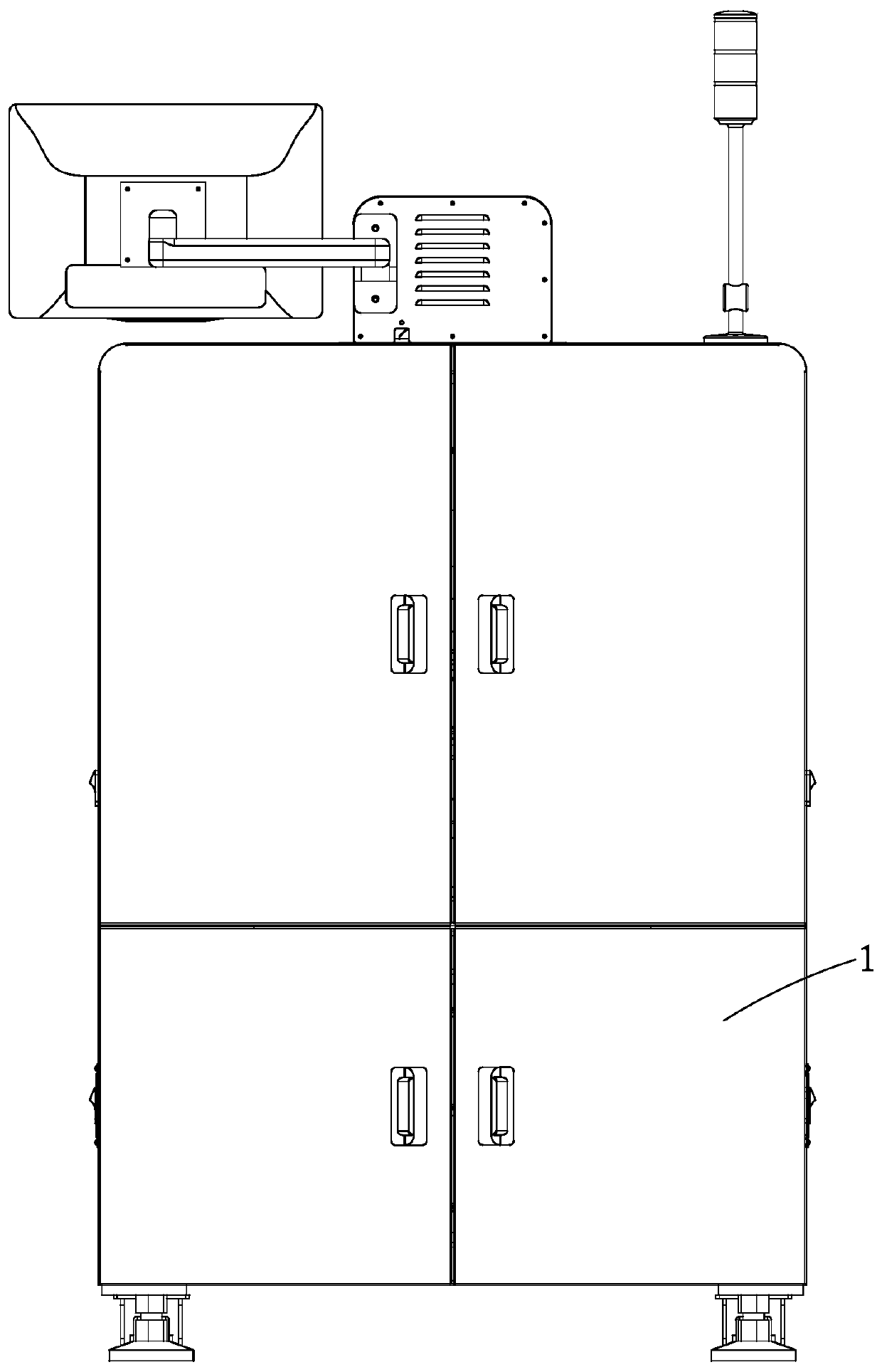
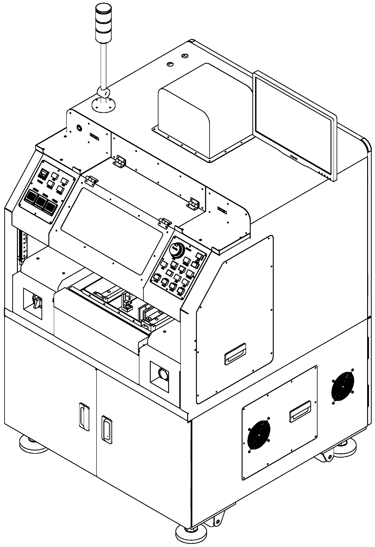
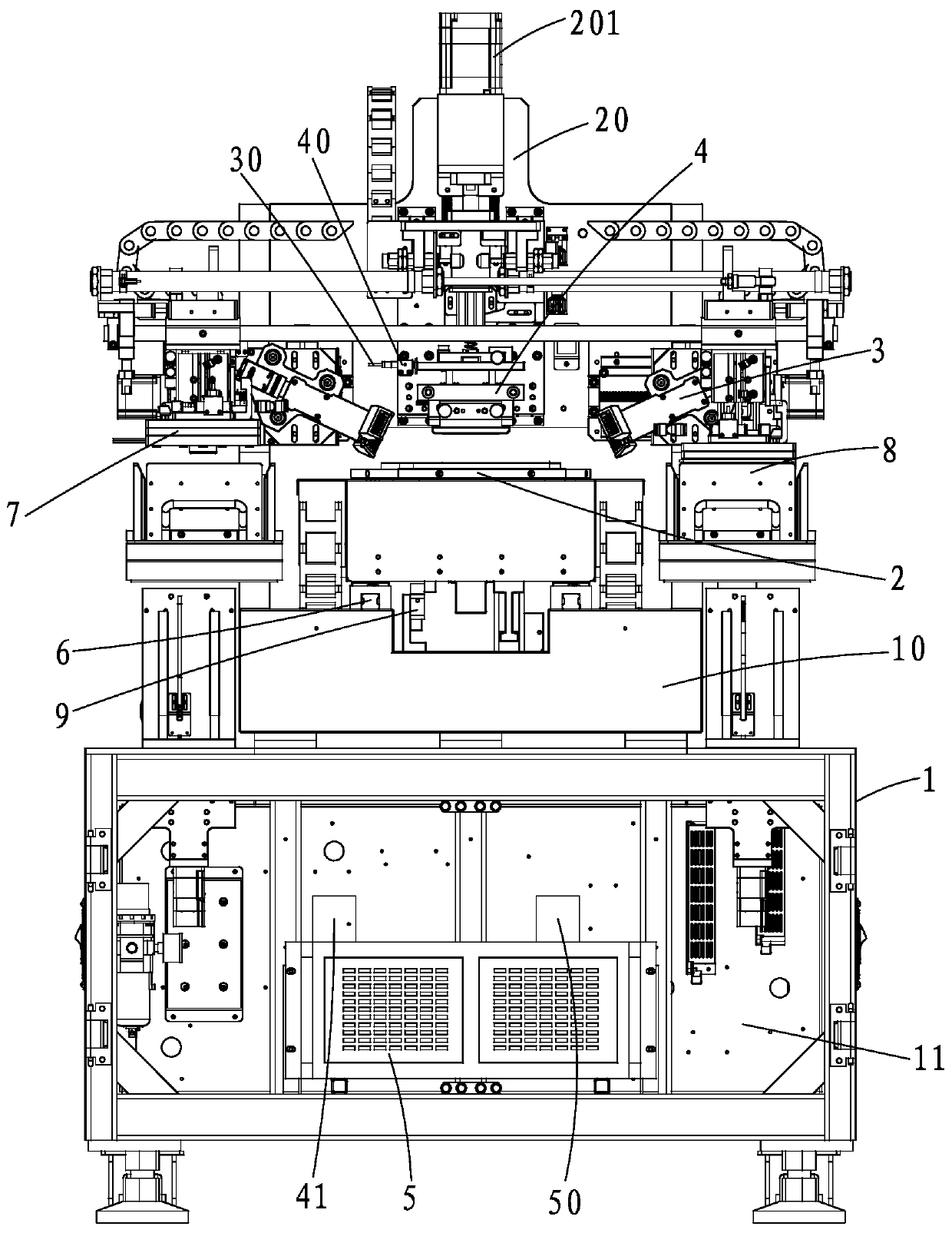
[0060] see Figures 1 to 21 As shown, the present invention provides an automatic cutting machine, including a body structure 1, a carrier 2, a detection and positioning mechanism 3, a cutting mechanism 4, a control system 5 and two guide rails 6, and a vacuum channel is provided inside the carrier 2, and the The left and right sides of the carrier 2 are also respectively provided with a vacuum suction cup, a transmission motor, a feeding mechanism 7 and a receiving mechanism 8; There is a DD direct drive servo rotation mechanism (not shown) that can allow the carrier 2 to rotate a certain angle relative to the carrier plate 21, and a direct drive mechanism 9 that can make the carrier plate 21 move linearly forward and backward is arranged below the carrier plate 21; the detection and positioning Mechanism 3 includes two groups of CCD detectors 31 arranged left and right, each group of said CCD detectors 31 includes a CCD lens 311, a motor 312, and a camera fine-tuning device....


PUM


Abstract

The invention discloses an automatic cutting machine. A groove is formed in the top of a supporting table, a direct-driving mechanism is installed in the groove, so that the installation height of thedirect-driving mechanism is reduced, a guide rail and a bearing plate only need to be connected through slide blocks, so that the gravity center of a bearing table and the gravity center of the bearing plate can be reduced, therefore the front-back pitching torque of the bearing plate and the bearing plate during high-acceleration starting and stopping can be reduced, the service life of the guide rail is prolonged, and the operation accuracy of the bearing table and the bearing plate is improved. The output force of a piston rod of an air cylinder can be accurately adjusted through an electric proportional valve, so that pressure of a knife holder module on a ceramic membrane is adjusted, adjustment is sensitive and convenient, the pressure can be correspondingly adjusted to the optimalstate according to different ceramic membranes, so that the ceramic membranes are guaranteed to be pressed tightly, the cutting stability is further guaranteed, and the cutting quality is guaranteed,the ceramic membranes are further prevented from being crushed, and extra damage to the ceramic membranes is avoided.

Description

technical field [0001] The invention relates to the field of electronic component manufacturing equipment, in particular to an automatic cutting machine. Background technique [0002] With the development of science and technology, there are more and more types of electronic products, with increasingly powerful functions and smaller and smaller volumes. This requires that the main electronic components in the manufacture of electronic products, such as capacitors, resistors, inductors, sensors, etc., should be as small as possible and as reliable as possible. At present, chip ceramic electronic components are mainly used, and their insulation, heat resistance, durability and other aspects all show excellent performance. As a result, the manufacture, sale and use of chip ceramic electronic components have flourished. [0003] When manufacturing chip ceramic electronic components, it is necessary to use a cutting machine to cut the ceramic diaphragm to obtain tiny electronic...

Claims


Application Information

Patent Timeline
IPC IPC(8): B28D1/22B28D7/00
CPCB28D1/22B28D7/00B28D7/005
Inventor 兰海王一鸣罗光裕
Owner 厦门海力拓自动化科技有限公司
Why Eureka
Try Eureka