Positioning mechanism for iron parts on left and right sides of automobile sunroof products

A technology for left and right side, car sunroofs, applied in household components, applications, household appliances, etc., can solve the problems of difficult flash cleaning process, waste of mold opening time, lengthened overall production process, etc., to improve labor efficiency and yield , Guarantee the specific position and angle, and reduce the effect of the secondary rework process

Pending Publication Date: 2019-07-09
福耀玻璃(苏州)有限公司
View PDF0 Cites 0 Cited by
  • Summary
  • Abstract
  • Description
  • Claims
  • Application Information

AI Technical Summary

Problems solved by technology

[0002] Automobile sunroof products are produced by injection molding the iron parts on both sides and the glass in the middle. The specific production process requires precise positioning of the iron parts to ensure the relative angle and position of the iron parts and the glass in the product. Existing The positioning mechanism of the iron parts on the left and right sides of the car sunroof product is the clamping block sealing strip. When opening the mold to pick up the parts, the clamping sealing strip needs to be ejected first, and then the iron parts are ejected. This process makes the position of the iron parts accurate. The degree is low, especially the vertical position degree is more prone to deviation
The program of clamping block structure is complicated. After the clamping block is ejected, it is opened and then ejected again. The overall production process is lengthened and the mold opening time is wasted.
On the other hand, the clamping block structure is easy to wear during the production process, resulting in flashes and flashes in the product. However, it is difficult to clean the flashes during the specific processing and will affect the overall production process. Failure to deal with the flashes will lead to Product appearance is bad

Method used


Image

  • Positioning mechanism for iron parts on left and right sides of automobile sunroof products
  • Positioning mechanism for iron parts on left and right sides of automobile sunroof products
  • Positioning mechanism for iron parts on left and right sides of automobile sunroof products

Examples


Embodiment

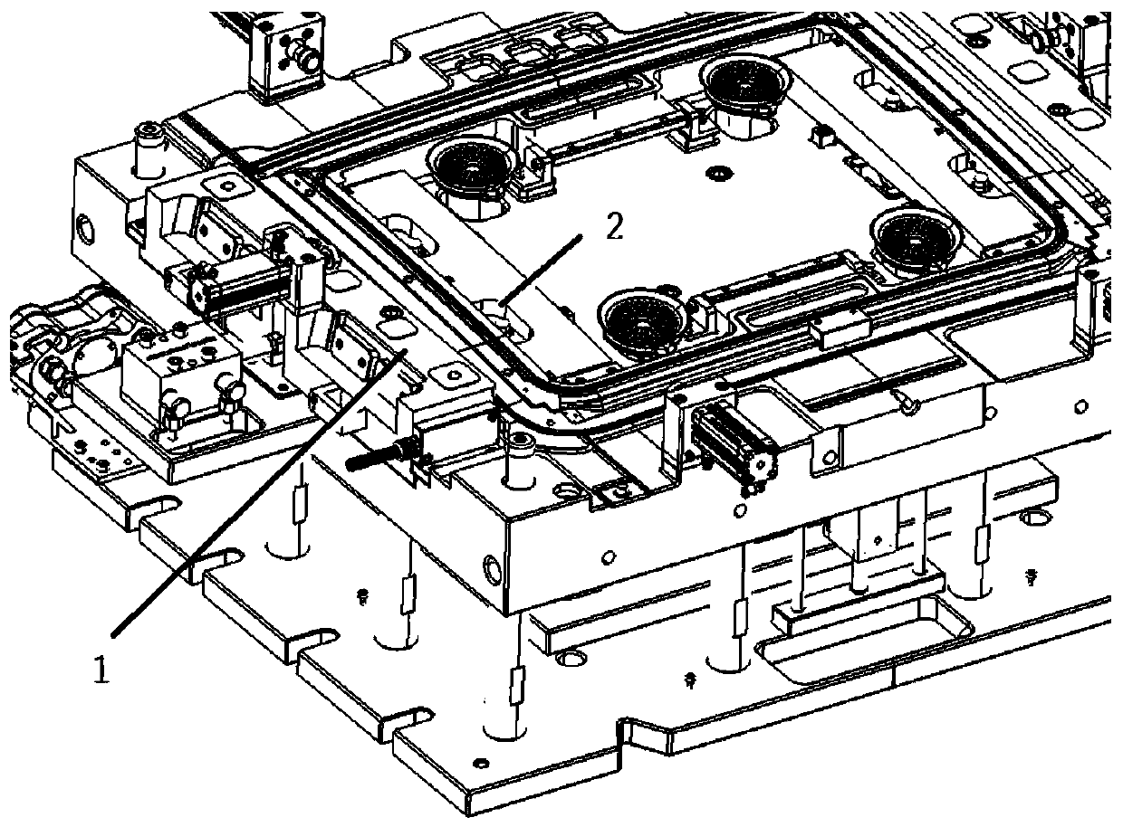
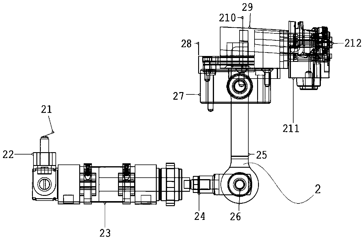
[0023] A positioning mechanism for iron parts on the left and right sides of a car sunroof product, used for positioning the iron parts in the injection molding process, including: an outer positioning component 1 and an inner positioning component 2 .

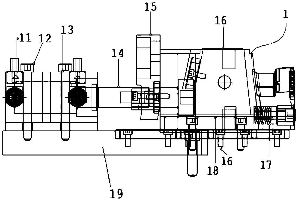
[0024] Wherein the outer positioning assembly 1 is located on the outer wall of the mold and is attached to one side of the iron piece, including a base plate 19 and a drive cylinder 13 fixed on the base plate 19, an oblique pressure block 15, a guide rail 18, and a ejection spring 17. The bottom plate 19 is fixed on the lower mold, the oblique pressure block 15 is used to cooperate with the slider located on the upper mold and clamp the upper and lower molds, and the guide rail 18 is movably connected with a side pull slider 16, One end of the ejection spring 17 is connected to the side of the side pull slider 16 near the iron piece, and the other end of the ejection spring 17 is against the iron piece. Vertically, the push r...


PUM


Abstract

The invention relates to a positioning mechanism for iron parts on left and right sides of automobile sunroof products. The positioning mechanism comprises an outer positioning assembly and an inner positioning assembly, wherein the outer positioning assembly comprises a bottom plate and a driving air cylinder, a diagonal pressing block, a guiding rail and an ejection spring, which are fixed on the bottom plate; the guiding rail is movably connected with a side pulling slider; one end of the ejection spring is connected with the side, close to an iron part, of the side pulling slider; the other end of the ejection spring abuts the iron part; the inner positioning assembly comprises a driving gas cylinder, an ejection member and a connecting rod member, which are fixed on a lower mold; a plurality of positioning pins are movably penetrated in the ejection member; the connecting rod member is used for transferring the pushing force of the driving gas cylinder to the ejection member; andone end of the positioning pin is pushed into a positioning hole or the positioning pin in the positioning hole is pulled back to ejection member through the ejection member. Compared with the prior art, the positioning mechanism saves the time of secondary ejection after ejecting and opening a clamping block, reduces the flashing phenomenon during the injection molding, and improves the product yield.

Description

technical field [0001] The invention relates to the field of injection molds, in particular to a positioning mechanism for iron parts on the left and right sides of automobile sunroof products. Background technique [0002] Automobile sunroof products are produced by injection molding the iron parts on both sides and the glass in the middle. The specific production process requires precise positioning of the iron parts to ensure the relative angle and position of the iron parts and the glass in the product. Existing The positioning mechanism of the iron parts on the left and right sides of the car sunroof product is the clamping block sealing strip. When opening the mold to pick up the parts, the clamping sealing strip needs to be ejected first, and then the iron parts are ejected. This process makes the position of the iron parts accurate. The lower the degree, especially the vertical position degree is more prone to deviation. The program of clamping block structure is co...

Claims


Application Information

Patent Timeline
IPC IPC(8): B29C45/14B29C45/26B29L31/30
CPCB29C45/14065B29C45/2606B29L2031/30
Inventor 张同广颜志强甘继波潘焰华
Owner 福耀玻璃(苏州)有限公司
Why Eureka
Try Eureka