Cable winding device

A cable winding and photoresistor technology is applied in the cable field, which can solve the problems of slow winding speed, time-consuming and laborious winding, and increase in the cost of cable winding, and achieves the effect of simple structure and convenient use.

Pending Publication Date: 2019-07-09
ZHUCHENG POWER SUPPLY CO STATE GRID SHANDONG ELECTRIC POWER CO +1
View PDF0 Cites 2 Cited by
  • Summary
  • Abstract
  • Description
  • Claims
  • Application Information

AI Technical Summary

Problems solved by technology

The diameter of the cable is large, so that the weight of the cable is much larger than that of ordinary wires at the same length, which is very inconvenient when storing and using the cable. The tool that is often used now is the cable roller, which is used to wind the cable for storage. It is also convenient for the use of subsequent cables. When using shorter cables, the existing cable rollers are more convenient to use, but there are the following problems when storing and using longer cables: thick cables over a kilometer are often wrapped around a The cable needs many people and a long time, and the artificial winding effect is not good, which affects the appearance, which will bring certain losses to the user; the existing cable winding devices generally cannot effectively adjust t...

Method used


Image

  • Cable winding device
  • Cable winding device
  • Cable winding device

Examples


Embodiment Construction

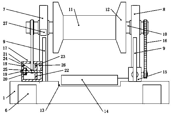
[0024] refer to Figure 1-Figure 8 As shown, the cable winding device includes a base plate 1, a corresponding left bracket 7 and a right bracket 8 are arranged on the length direction of the upper part of the base plate 1, and the left bracket 7 and the right bracket 8 are pierced with rollers arranged along the length direction of the base plate 1. The shaft 10, the bottom plate 1 between the left bracket 7 and the right bracket 8 is provided with a groove 13, and an electric storage box 14 is installed in the groove 13, and an electric box 15 is installed on the bottom plate 1 on one side of the right bracket 8, A speedometer 17 is installed on the base plate 1 on one side of the left support 7 .

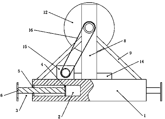
[0025] refer to figure 1 and figure 2 As shown, the bottom plate 1 is a rectangular bottom plate, and two embedded holes 2 extending into the bottom plate 1 are provided on both side walls of the bottom plate 1 in the width direction, and the embedded holes 2 are symmetrically...


PUM


Abstract

The invention discloses a cable winding device. The device comprises a bottom plate, wherein a left support and a right support are arranged on the upper part of the bottom plate, one side of the leftsupport is provided with a speed measurer, the speed measurer is connected with the rolling shaft through a belt, the speed measurer comprises a shell, a speed measuring shaft is arranged in the shell in a penetrating mode, the speed measuring shaft is sequentially provided with a speed limiter, a belt roller and a speed measuring disc, a light passing hole is formed in the speed measuring disc,a light emitting light source is arranged on the inner wall of one end of the shell, a photoresistor is arranged on the inner wall of the other end of the shell, the speed limiter comprises a fixing sleeve, a fixing sleeve is arranged on the speed measuring shaft in a sleeved mode, a clamping opening is formed in the inner wall of the fixing sleeve, an inner rotating disc is connected to the speedmeasuring shaft in a key mode, a T-shaped groove is formed in the outer wall of the inner rotary disc, a plurality of buckles are arranged in the t-shaped groove, the buckle comprises a base, the upper part of the base is provided with a hinging seat, and the end part, away from the inner rotating disc, of the speed limiting sheet can be inserted into the clamping opening to be arranged. The cable winding device has the technical effects of being simple in structure, convenient to use, suitable for winding of cables of different types, and capable of adjusting the speed of winding and releasing the cables.

Description

technical field [0001] The invention relates to the technical field of cables, in particular to a cable winding device. Background technique [0002] A cable is a wire made of one or more mutually insulated conductors or sheathed with insulation, and is used to transmit power or signals from one place to another. The diameter of the cable is large, which leads to the weight of the cable being much larger than that of ordinary wires at the same length, which is very inconvenient when storing and using the cable. The tool that is often used now is the cable roller, which is used to wind the cable for storage. It is also convenient for the use of subsequent cables. When using shorter cables, the existing cable rollers are more convenient to use, but there are the following problems when storing and using longer cables: thick cables over a kilometer are often wrapped around a The cable needs a lot of people and a long time, and the effect of manual winding is not good, which af...

Claims


Application Information

Patent Timeline
IPC IPC(8): B65H54/44B65H54/553B65H63/00
CPCB65H54/44B65H54/553B65H63/00B65H2701/34
Inventor 张旭盈李臣径王瑞宁周其朋隋东阳张琦苏宁李兆欣徐明伟王朋胡雪冬马士胜惠三军郭垒郎益伟冯恩刚赵勇
Owner ZHUCHENG POWER SUPPLY CO STATE GRID SHANDONG ELECTRIC POWER CO
Why Eureka
Try Eureka