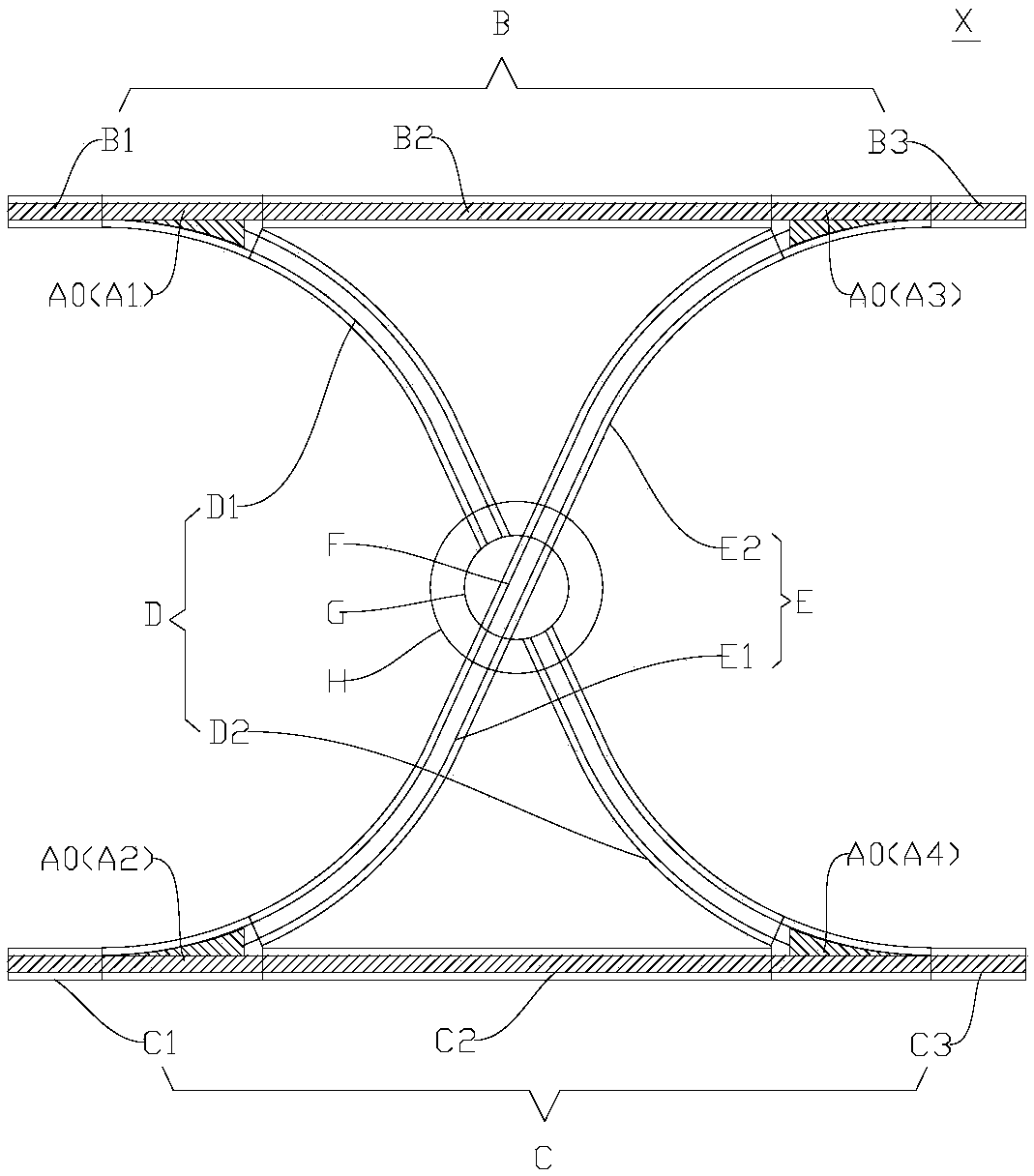
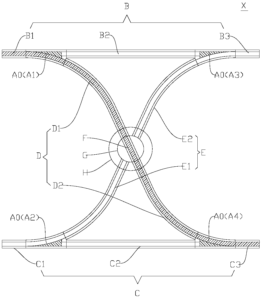
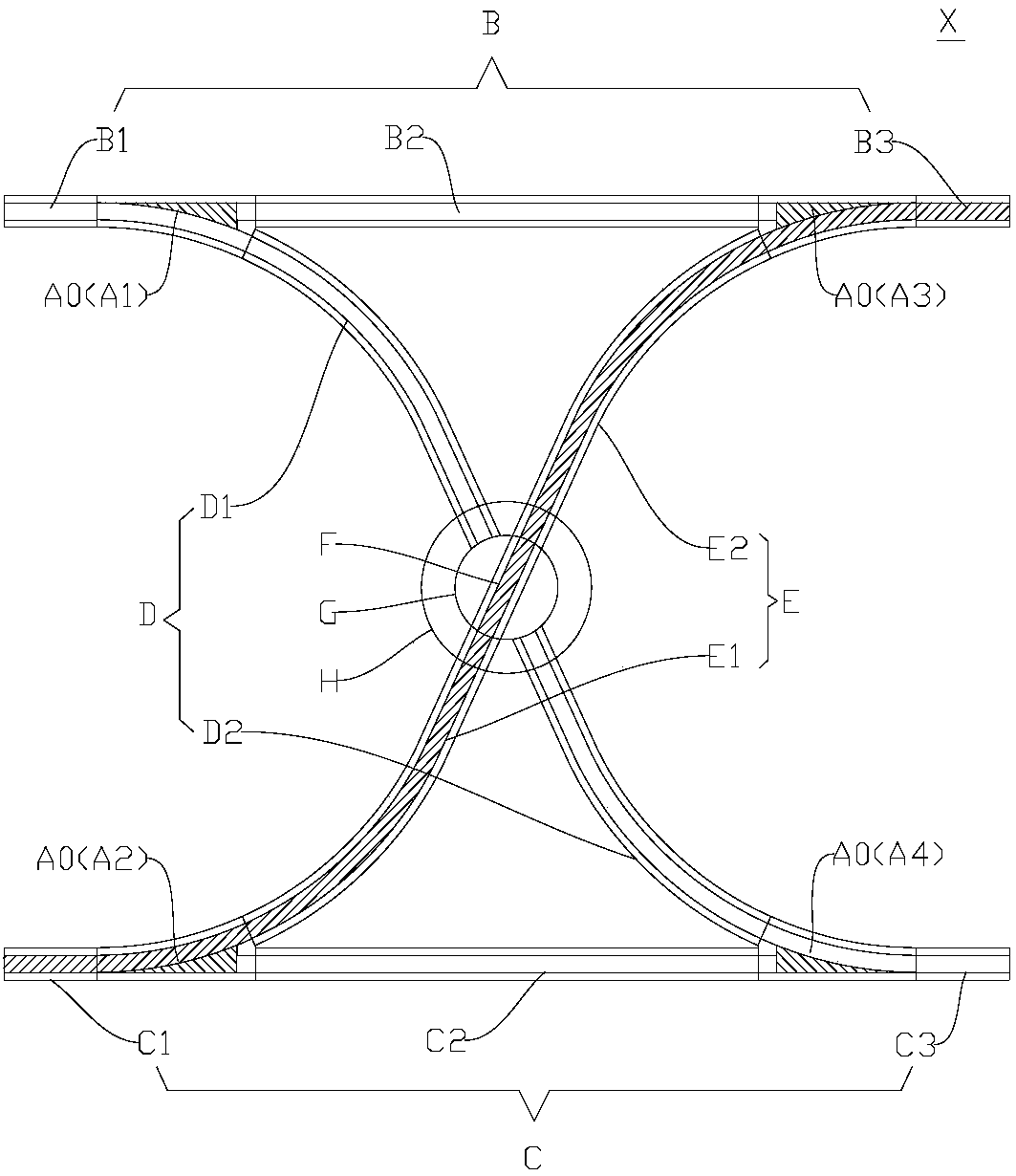
Crossover turnout and rail transit system with same
A turnout and crossover technology, which is applied in the field of rail transit systems, can solve the problems of time-consuming and labor-intensive operation of moving turnout beams, heavy turnout beams, and easy damage of turnout beams, etc., to achieve convenient and reliable switching, light switch, and good economy Effect
- Summary
- Abstract
- Description
- Claims
- Application Information
AI Technical Summary
Problems solved by technology
Method used
Image
Examples
Embodiment 1
[0122] Such as Figure 14-Figure 21 As shown, the fixed beam 11 includes a connecting beam 114 connected between the first side beam 111 and the second side beam 112 , and the movable beam 12 is equipped with a rolling device between the movable beam 12 and the connecting beam 114 . Thus, during the movement of the movable beam 12 relative to the fixed beam 11, the movable beam 12 can form a rolling friction fit with the connecting beam 114 through the rolling device, thereby reducing frictional resistance and friction loss, and improving the portability and ease of movement of the movable beam 12. Reliability and reduced friction damage.
[0123] Preferably, as Figure 14 As shown, the above-mentioned connecting beam 114 can be used as the supporting wall of the driving passage (that is, the above-mentioned supporting beam 113). When the single switch A0 is a suspension switch, the connecting beam 114 can be used as the top wall of the driving passage. Thus, the structure ...
Embodiment 2
[0138] The second embodiment is substantially the same as the first embodiment above, and the same components are designated with the same reference numerals. The difference lies in that the driving device of the second embodiment is different from the driving device of the first embodiment above.
[0139] Such as Figure 22-Figure 27 As shown, the driving device 3 includes: a first connecting rod 321, a second connecting rod 322 and a driving cylinder 323 (such as an electric cylinder, an air cylinder or a hydraulic cylinder), the first end of the first connecting rod 321 is hinged with the movable beam 12, the second The two ends of two connecting rods 322 are respectively hinged with the second end of the first connecting rod 321 and the fixed beam 11, and the drive cylinder 323 includes a cylinder barrel 3231 which is located on the fixed beam 11 and is telescopic along the cylinder barrel 3231 and the free end is connected to the second end of the first connecting rod 321....
Embodiment 3
[0143] The third embodiment is substantially the same as the first embodiment above, and the same components are designated with the same reference numerals. The difference lies in that the driving device of the third embodiment is different from the driving device of the first embodiment above.
[0144] Such as Figure 28 As shown, the drive device 3 is: a drive motor 33, the output shaft of the drive motor 33 is directly connected with the first scroll wheel 511 to drive the first scroll wheel 511 to roll on the connecting beam 114, that is to say, when the drive motor 33 output turns When the torque is turned, the first rolling wheel 511 can roll, thereby driving the first trolley 61 and the movable beam 12 to walk. Therefore, the structure can be further simplified and the reliability of the control can be improved through the direct drive of the motor 3111 , and the installation of the driving device 3 is simple, economical and convenient for maintenance. Preferably, the...
PUM
 Abstract
Description
Claims
Application Information
 - R&D
- Intellectual Property
- Life Sciences
- Materials
- Tech Scout
- Unparalleled Data Quality
- Higher Quality Content
- 60% Fewer Hallucinations
Browse by: Latest US Patents, China's latest patents, Technical Efficacy Thesaurus, Application Domain, Technology Topic, Popular Technical Reports.
© 2025 PatSnap. All rights reserved.Legal|Privacy policy|Modern Slavery Act Transparency Statement|Sitemap|About US| Contact US: help@patsnap.com


