Supporting structure for rock roadbed heightening and construction method

A technology for retaining structures and subgrades, which is applied in basic structure engineering, underwater structures, roads, etc., can solve the problem of affecting the stability and normal use of cantilever retaining walls, and cannot guarantee the overall stability of heightened structures. Problems such as external inclination and deformation of the vertical wall of the retaining wall are achieved to ensure stability and normal use, improve self-supporting capacity, and reduce cost

Inactive Publication Date: 2019-07-09
DALIAN JIAOTONG UNIVERSITY
View PDF6 Cites 2 Cited by
  • Summary
  • Abstract
  • Description
  • Claims
  • Application Information

AI Technical Summary

Problems solved by technology

[0003] 1. The design height of the existing cantilever retaining wall is not enough and needs to be increased
[0004] 2. Heightening the cantilever retaining wall will increase the earth pressure at the bottom of the retaining wall, which will cause the wall to overturn, crack and other damage
[0005] 3. The vertical wall of the cantilever retaining wall will produce outward deformation. If the deformation of the vertical wall continues to accumulate, it will seriously affect the stability and normal use of the cantilever retaining wall itself
[0007] 1. The original cantilever retaining wall is demolished, and other supporting structures such as the buttress retaining wall structure are built; however, there are problems of damaging the environment, troublesome construction and high cost
[0008] 2. New unloading plate or pallet structure, but it will cause the deformation of the vertical wall of the cantilever retaining wall
[0009] 3. Add oblique prestressed anchor cables or vertical stress anchor cables to the original cantilever retaining wall; but a single measure cannot guarantee the overall stability of the elevated structure

Method used


Image

  • Supporting structure for rock roadbed heightening and construction method
  • Supporting structure for rock roadbed heightening and construction method
  • Supporting structure for rock roadbed heightening and construction method

Examples


Embodiment Construction

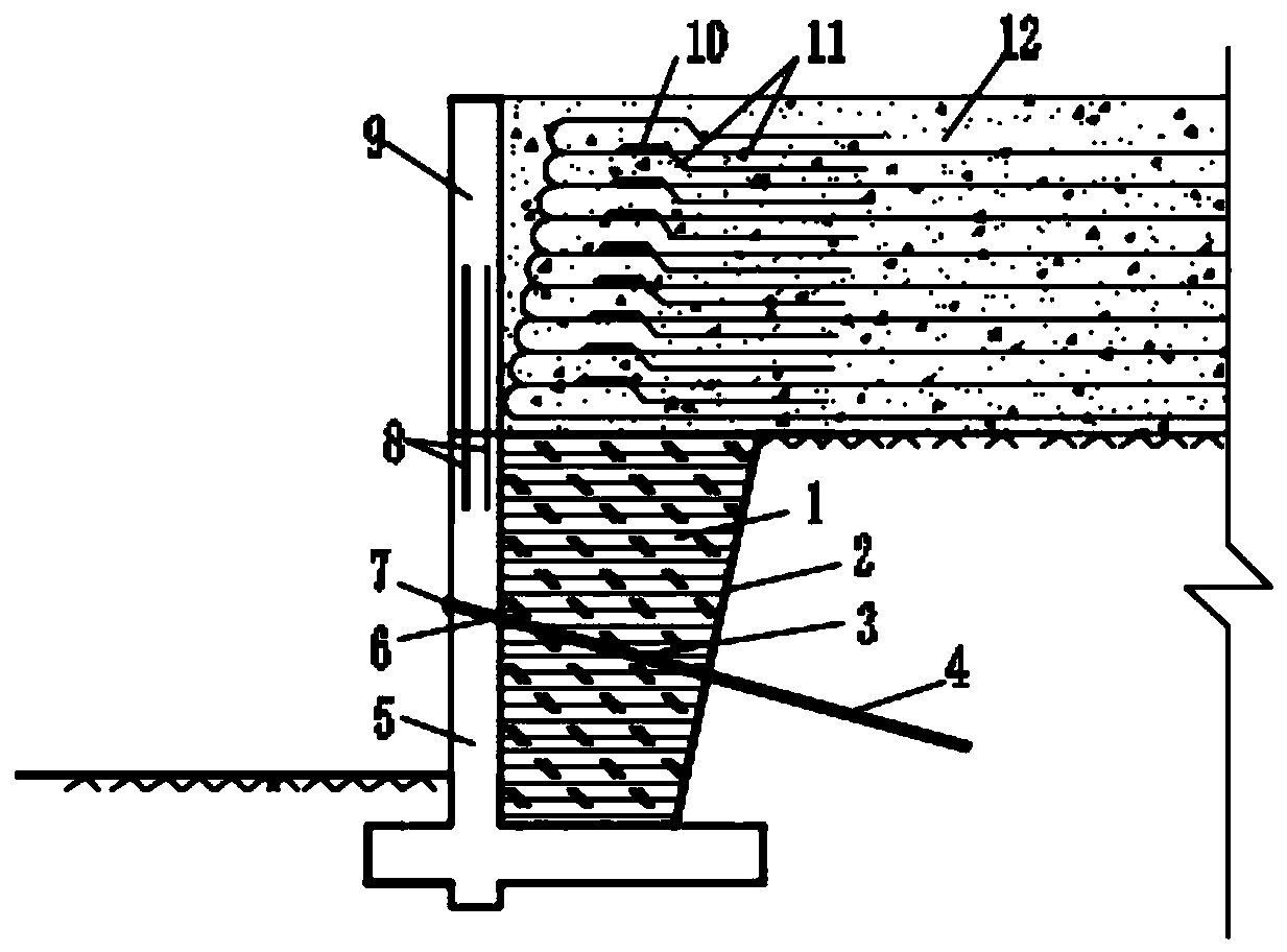
[0040] The present invention will be further described below in conjunction with the accompanying drawings. Such as Figure 1-4 As shown, a retaining structure for raising rocky subgrades, including rocky subgrades, prestressed anchor cables, connecting rods 8, wall panels 9, connecting rods 10 and geogrids 11;

[0041] The rocky subgrade includes a cantilever retaining wall 5, miscellaneous fill 1 and rock slope 2, and the miscellaneous fill 1 is buried between the cantilever retaining wall 5 and the rock slope 2;

[0042] The prestressed anchor cables are arranged obliquely in the rocky subgrade.

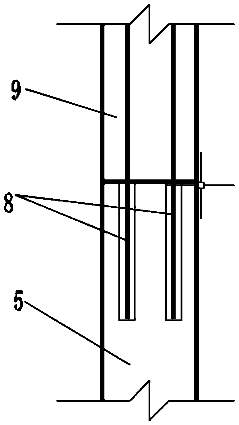
[0043] A wall panel 9 is arranged on the top of the cantilever retaining wall 5, and the wall panel 9 is connected with the cantilever retaining wall 5 through a connecting rod 8;

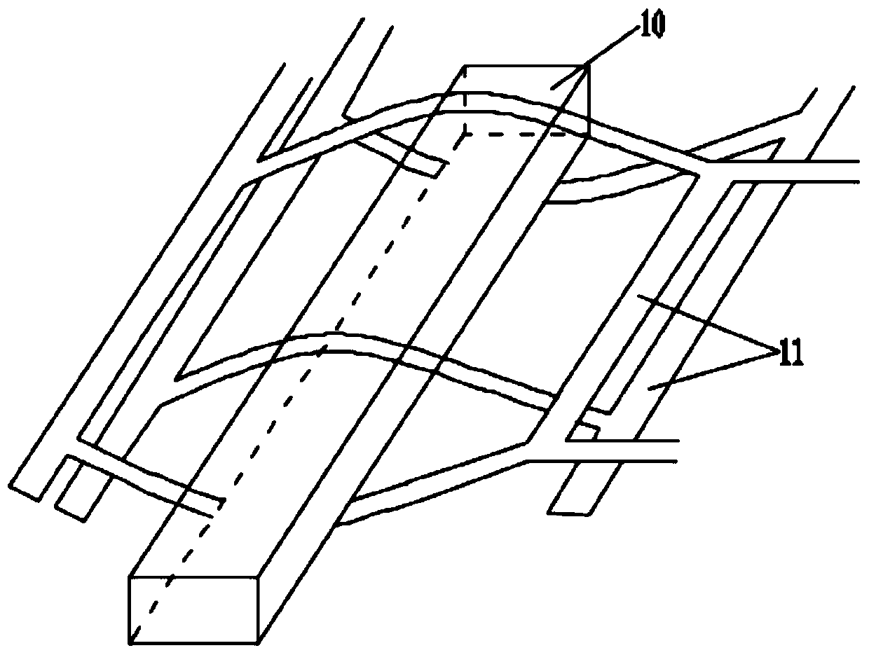
[0044] The rocky subgrade inside the wall panel 9 is provided with multi-layer geogrid 11 and filler 12 to form a raised subgrade.

[0045] Further, the prestressed anchor cable is composed of an an...


PUM


Abstract

The invention discloses a supporting structure for rock roadbed heightening and a construction method. The structure comprises a rock roadbed, prestressed anchor cables, a connecting rod, a wall panel, a connecting rod and geogrids. The prestressed anchor cables are obliquely arranged in the rock roadbed, the wall panel is arranged at the top of a cantilever type retaining wall and connected withthe cantilever type retaining wall through the connecting rod; a plurality of layers of the geogrids and fillers are arranged on the rock roadbed on the inner side of the wall panel to form a heightened roadbed. The shear resistance and rigidity of the cantilever type retaining wall can be effectively improved by installing the prestressed anchor cables, so that the deformation of the vertical wall is effectively reduced, and the stability and the normal use of the cantilever type retaining wall are ensured. The mounting of the wall panel can effectively improve the use height of the cantilever type retaining wall, and can ensure the stability of the plurality of layers of the geogrids. The prestressed anchor cables and the geogrids belong to flexible structures and are high in shock resistance, an existing cantilever type retaining wall is not dismounted, and thus the manufacturing cost is reduced.

Description

technical field [0001] The invention relates to road construction technology, in particular to a retaining structure and construction method for raising rocky roadbed. Background technique [0002] In the process of road reconstruction, it is difficult to avoid the situation that the elevation of the road surface increases, and the original supporting structure must be raised. The cantilever retaining wall is one of the commonly used retaining structures for fill slopes. The applicable height of the cantilever retaining wall should not exceed 6m. In actual engineering, the following problems may occur: [0003] 1. The design height of the existing cantilever retaining wall is not enough and needs to be increased. [0004] 2. Heightening the cantilever retaining wall will increase the earth pressure at the bottom of the retaining wall, which will cause the wall to overturn, crack and other damage. [0005] 3. The vertical wall of the cantilever retaining wall will produce o...

Claims


Application Information

Patent Timeline
Patent Type & Authority Applications(China)
IPC IPC(8): E02D29/02E02D17/20E02D3/00E01C3/04E02D5/76
CPCE01C3/04E02D3/005E02D5/76E02D17/20E02D29/02E02D29/0233
Inventor 王海涛李志明涂兵雄吴跃东刘维孙昊宇古兴康苏鹏庄心欣郭涛
Owner DALIAN JIAOTONG UNIVERSITY
Why Eureka
Try Eureka