[0032] Aiming at the technical problem that the working fluid in the cryogenic cryotherapy equipment in the prior art needs to be transported separately, which limits the application of the equipment, this article has conducted in-depth research and proposed a technical solution to solve the above technical problems.
[0033] In order to enable those skilled in the art to better understand the technical solutions of the present invention, the present invention will be further described in detail below with reference to the accompanying drawings and specific embodiments.
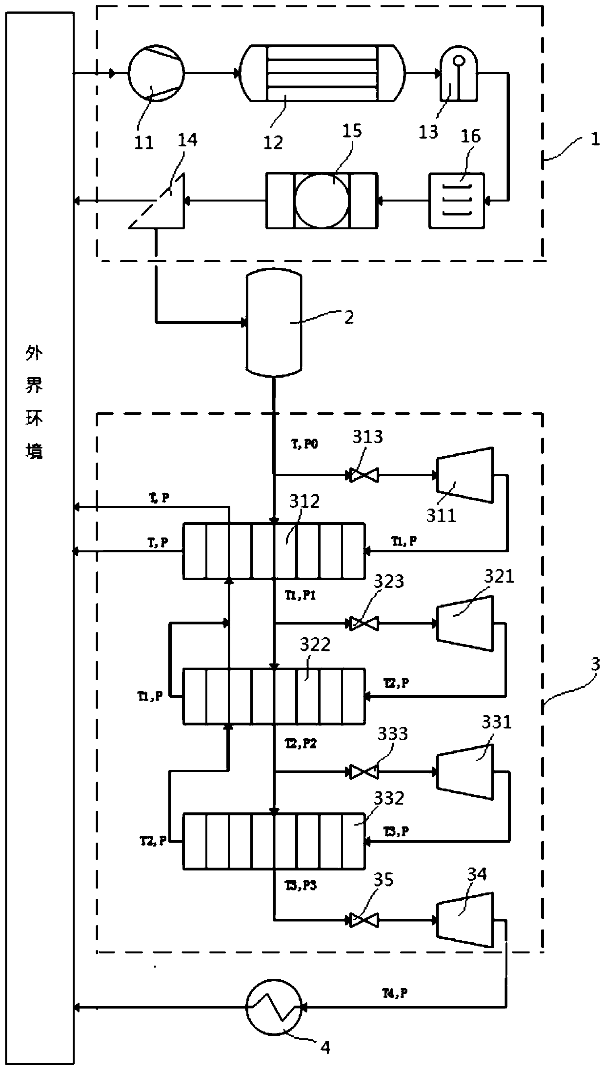
[0034] Please refer to figure 1 , figure 1 It is a schematic diagram of a cryotherapy device in an embodiment of the present invention; the arrow in the figure indicates the flow direction of the working fluid.
[0035] The present invention provides a cryogenic cryotherapy equipment, including a therapeutic application body 4, which can be an ablation needle, and of course, it can also be other similar medical work equipment that requires cryogenic working fluid.
[0036] The cryogenic cryotherapy equipment in the present invention further includes a working fluid generator 1, a pressure storage tank and a throttling refrigeration component.
[0037] The working medium generator 1 is used to separate the working medium required by the treatment application body 4 from the air, that is, the working medium generator 1 can separate one gas working medium or several gas working mediums from the air as treatment Apply the working fluid of Ontology 4. The type of working medium separated by the working medium generator 1 can be determined according to the type of the treatment application body 4, and the working medium can be nitrogen, oxygen or argon. Correspondingly, the working fluid generator 1 should have one or several operating conditions, such as nitrogen operating conditions, oxygen operating conditions and argon operating conditions. When the working medium generator 1 is in a nitrogen working state, the working medium generator 1 can separate the nitrogen working medium from the air. When the working medium generator 1 is in an oxygen tooling state, the working medium generator 1 can separate the oxygen working medium from the air.
[0038] Of course, the working medium that can be separated by the working medium generator 1 is not limited to the above-mentioned ones, and may also be carbon dioxide or other media. Of course, the gas source is not limited to air, and can also be other types of gas containing the required working fluid. This article takes air as an example to continue to introduce the technical solution.
[0039] The pressure storage tank is used to store the working fluid generated by the working fluid generator 1.
[0040] The specific structure of the working fluid generator 1 can take many forms, and a preferred specific implementation is given in this article. The working medium generator 1 may include one or more of an air compressor 11, a cooler 12, an oil and gas separator 13, a dryer 16, a filter 15, a gas separator 14, and so on. The air is compressed in the air compressor 11, the pressure increases, the temperature rises, and becomes high temperature and high pressure air; then it enters the cooler 12, the temperature decreases, and becomes normal temperature and high pressure air; then it enters the oil and gas separator 13 to separate the air from the air. The lubricating oil from the compressor; then enters the dryer 16 to remove the moisture in the air; then enters the filter 15 to remove impurity particles and becomes the normal temperature and high pressure dry clean air; then enters the gas separator 14 to achieve air separation. High-pressure nitrogen at room temperature is generated, and other impurity gases are discharged from the equipment.
[0041] The air compressor 11 may be a screw type, a piston type, a centrifugal type or a combination of more than one.
[0042] The gas separator 14 may be of an adsorption type or a membrane separation type.
[0043] Finally, the nitrogen at normal temperature and pressure is stored in the pressure storage tank 2. The volume and working pressure of the pressure tank 2 can be determined according to the specific application environment, for example: the volume is roughly 1ml-100m 3; Working pressure can be 0-1000MPa.
[0044] The throttling refrigeration component 3 is arranged between the air outlet of the pressure storage tank 2 and the treatment application body 4, and is used to cool the nitrogen gas flowing out of the pressure storage tank 2 to obtain a working fluid that meets the temperature required by the treatment application body 4 to work.
[0045] That is to say, the main function of the throttling refrigeration component 3 is to throttle and cool the gas flowing out of the pressure storage tank 2 to obtain the working fluid required by the treatment application body 4.
[0046] The specific structure of the throttling refrigeration component 3 that can realize the above-mentioned functions can be in various forms, and a specific structure will be described in detail below. Of course, those skilled in the art should understand that the structure of the throttling refrigeration component 3 is not limited to the structure described herein, and may also be other structures as long as the above functions can be realized.
[0047] In addition, the communication pipeline of the pressure storage tank 2 and the throttling refrigeration component 3, the gas outlet of the throttling refrigeration component 3 and the working fluid inlet communication pipeline of the treatment application body 4 in the present invention are all provided with a flow control valve to control the corresponding Gas flow in the pipeline. In this way, it is convenient to reasonably control the flow of the working fluid according to the specific working conditions of the treatment application body 4 to meet the requirements of different working conditions.
[0048] Compared with the prior art, the present invention is specifically provided with a working medium generator 1 capable of separating working medium from the air. The working medium produced by the working medium generator 1 can pass through multiple stages under the action of the throttling refrigeration component 3. The throttling and cold recovery are converted into working fluids under predetermined temperature and pressure conditions to provide working fluids for the treatment application body 4 to achieve normal disease treatment of the treatment application body 4. That is, the cryogenic cryotherapy equipment of the present invention can realize the self-supply of working fluid without the need for special gas cylinders for gas supply, thereby overcoming the limitations of the prior art gas cylinder transportation requirements and high costs for the application range of the therapeutic application body 4; Realize that the room temperature gas can achieve extremely low treatment temperature through its own multi-stage throttling and cold recovery without pre-cooling, thereby overcoming the poor effect of single-stage gas throttling in the prior art and the need to pre-cool the gas The shortcomings of the treatment application body 4 greatly improve the popularity and treatment effect of the treatment application body 4, and provide patients with the convenience of disease treatment, so that the treatment application body 4 can benefit more patients and help improve the level of social medical services.
[0049] In a specific embodiment, the throttling refrigeration component 3 may include at least one throttling heat exchange unit. The throttling heat exchange unit includes a choke and a heat exchanger. The main function of the choke is to counteract the gas flowing through it. The fluid expands to reduce the temperature and pressure of the working fluid.
[0050] The restrictor may be one or a combination of a small orifice restrictor, an orifice restrictor, a throttle valve, a turbine, and a slit restrictor.
[0051] The heat exchanger can be one or a combination of plate-fin type, plate type, shell-and-tube type, and sleeve type.
[0052] The heat exchanger includes a first heat exchange channel and a second heat exchange channel. When in the working state, the fluid flowing through the first heat exchange channel exchanges heat with the fluid flowing through the second heat exchange channel; The high-temperature medium and low-temperature medium for heat exchange respectively flow through the first heat exchange channel and the second heat exchange channel. The structure of the first heat exchange channel and the second heat exchange channel can refer to the prior art, which will not be repeated here.
[0053] The throttle heat exchange unit can be an integral component, that is, the throttle and the heat exchanger are integrated into the same shell to form a whole. Of course, the throttle heat exchange unit can also be a separate component, that is, the throttle and the heat exchange The device is an independent component, and the two are connected by pipelines, which facilitates maintenance and reduces maintenance costs.
[0054] The air inlet of the throttle heat exchange unit is connected to the air inlet of the throttle and the inlet of the first heat exchange channel through two pipes, and the air outlet of the throttle is connected to the inlet of the second heat exchange channel, the first heat exchange channel The outlet is connected to the air inlet of the next-stage throttling heat exchange unit or the working fluid inlet of the treatment application body 4.
[0055] Set the number of throttling heat exchange units according to the temperature and pressure conditions of the initial working fluid in the pressure storage tank 2 and the temperature and pressure requirements of the final working fluid. The number of throttling heat exchange units can be one or two Or three or more. This article takes the setting of three throttling heat exchange units as an example to continue to introduce the technical solutions and technical effects.
[0056] In a specific embodiment, the number of throttling heat exchange units in the cryogenic energy cryotherapy equipment can be three, which are defined as: the first-stage throttling heat exchange unit, the second-stage throttling heat exchange unit, and the second-stage throttling heat exchange unit. Three-stage throttling heat exchange unit.
[0057] It should be noted that the working fluid (Ti, Pi) in the following refers to a working fluid with a temperature of Ti and a pressure of Pi, only for the sake of brevity of the description of the technical solution.
[0058] Among them, the inlet of the first-stage throttling heat exchange unit is connected to the outlet of the pressure storage tank 2. When working, the working fluid (T, P0) in the pressure storage tank 2 flows into the first-stage throttling heat exchange unit through the pipeline, and is divided into Two paths, one of which flows into the first-stage throttle 311 of the first-stage throttling heat exchange unit, the temperature and pressure are reduced after the first-stage throttle 311 is throttled and expanded, and after flowing out of the first-stage throttle 311 The working fluid temperature and pressure are respectively T1 and P, namely working fluid (T1, P). The working fluid (T1, P) flowing out of the first-stage restrictor 311 exchanges heat with another working fluid (T, P0) in the first-stage heat exchanger 312, if the pressure loss of the pipeline and resistance elements is not considered , The working fluid (T1, P) becomes working fluid (T, P) after heat exchange, and the working fluid (T, P0) becomes working fluid (T1, P1) after heat exchange.
[0059] The working fluid (T, P) after heat exchange can be directly discharged to the external environment, that is, the outlet of the second heat exchange channel of the heat exchanger (first-stage heat exchanger 312) in the first-stage throttling heat exchange unit is connected to the outside surroundings. Of course, the air source device that provides the air source in the working fluid generator 1 can be reused again, that is, the outlet of the second heat exchange channel of the heat exchanger in the first-stage throttling heat exchange unit is connected to the working medium. The mass generator 1 provides the air source device for the air source.
[0060] The working fluid (T1, P1) flowing out from the outlet of the first heat exchange channel of the first-stage heat exchanger 312 enters the air inlet of the second-stage throttling heat exchange unit again, and the same goes for the second-stage throttling heat exchange unit There are two ways for the air intake, all the way through the second-stage throttle 321, after the second-stage throttle, the temperature and pressure decrease and become the working fluid (T2, P), and the working fluid (T2, P) continues It flows into the second-stage heat exchanger 322 and exchanges heat with another working fluid (T1, P1) inside the second-stage heat exchanger 322. After the heat exchange of the working fluid (T2, P), the temperature rises and becomes the working fluid ( T1, P), working fluid (T1, P1) after the heat exchange, the temperature decreases and becomes working fluid (T2, P2).
[0061] Further, the working fluid (T2, P2) flowing out from the outlet of the first heat exchange channel of the second-stage heat exchanger 322 enters the air inlet of the third-stage throttling heat exchange unit again, and the same applies to the third-stage throttling The air inlet of the heat exchange unit is divided into two paths, one way flows through the third-stage restrictor 331. After the third-stage restrictor, the temperature and pressure decrease and become the working fluid (T3, P), the working fluid (T3, P) Continue to flow into the third-stage heat exchanger 332, exchange heat with another working fluid (T2, P2) inside the third-stage heat exchanger 332, and the temperature of the working fluid (T3, P) after the heat exchange becomes Working fluid (T2, P), working fluid (T2, P2) after the heat exchange, the temperature decreases and becomes working fluid (T3, P3).
[0062] The working fluid (T1, P) can flow directly from the outlet of the second heat exchange channel to the external environment or the air source device. Of course, considering that the temperature of the working fluid (T1, P) is still relatively low at this time, the gas can be further passed into the interior of the first-stage heat exchanger 312 and into the working fluid (T, P0) inside the first-stage heat exchanger 312 Perform heat exchange to improve heat utilization efficiency.
[0063] The homogeneous materials (T2, P) can also flow directly from the outlet of the third heat exchange channel to the external environment or the air source device. Of course, it is also possible to pass into the second-stage heat exchanger 322 to exchange heat with the working fluids (T1, P1) flowing into the second-stage heat exchanger 322 to improve heat utilization efficiency.
[0064] In other words, when the number of throttling heat exchange units is greater than or equal to two (N is greater than or equal to 2), the working fluid flowing out of the second heat exchange channel of the next stage heat exchanger can be passed to the previous stage heat exchanger Inside, the cold energy is recovered again. In order to improve the stability of the system, the heat exchanger in the former N-1 stage throttling heat exchange unit further includes a third heat exchange channel. When in operation, the fluid flowing through the third heat exchange channel flows through the The fluids of the second heat exchange channel both exchange heat with the fluid flowing through the first heat exchange channel; the outlet of the second heat exchange channel of the heat exchanger of the N th throttling heat exchange unit communicates with the N th -1 Throttle the entrance of the third heat exchange channel of the heat exchanger of the heat exchange unit.
[0065] In this way, the fluid in the second heat exchange channel and the fluid in the third heat exchange channel are independent of each other, and work does not affect each other, which is beneficial to system stability.
[0066] Further, each of the above-mentioned throttling refrigeration components 3 may also include a terminal throttle 34, which is arranged downstream of the last-stage throttling heat exchange unit, and the heat exchanger in the last-stage throttling heat exchange unit The outlet of the first heat exchange channel communicates with the inlet of the terminal restrictor 34, and the outlet of the terminal restrictor 34 communicates with the working fluid inlet of the treatment application body 4.
[0067] After the working fluid (T3, P3) is throttled and expanded by the terminal throttle 34, the temperature and pressure are reduced, and the working fluid (T4, P) is obtained. The working fluid (T4, P) enters the ablation needle for cryotherapy. In the above description, the temperature T> T1> T2> T3> T4, pressure P0≥P1≥P2≥P3≥P.
[0068] In this way, the temperature and pressure of the working fluid that finally flows into the treatment application body 4 can be accurately adjusted.
[0069] Proper piping design and flow distribution are easy to achieve a small heat exchange temperature difference, so the heat exchange temperature difference can be ignored without major deviations in the calculation results. It is assumed that the outlet temperature of the high temperature side of the heat exchanger after heat exchange is low Inlet temperature on the side. Taking nitrogen as the working fluid as an example, by consulting the physical parameters of nitrogen and calculating, four sets of results are given in Table 1.
[0070] Table 1
[0071]
[0072] Further, a terminal regulating valve 35 is provided between the terminal throttle 34 and the outlet of the first heat exchange channel of the heat exchanger of the last-stage throttling heat exchange unit.
[0073] In the foregoing embodiments, the inlet pipes of the throttles of the throttle heat exchange units at all levels are provided with regulating valves for adjusting the flow of the working fluid flowing into the corresponding throttle at the inlet of the throttle heat exchange unit, such as figure 1 As shown, the first-stage regulating valve 313, the second-stage regulating valve 323, and the third-stage regulating valve 333, the first-stage regulating valve 313 is used to regulate the working fluid entering the first-stage throttle 311; the second-stage regulating valve 323 is used to adjust the working fluid entering the second-stage throttle 321; the third-stage regulating valve 333 is used to adjust the working fluid entering the third-stage throttle 331.
[0074] The number of throttles in the above-mentioned throttle refrigeration unit can be one or more. The number of restrictors is preferably one.
[0075] The specific structure of each regulating valve can refer to the prior art.
[0076] The cryotherapy equipment provided by the present invention has been described in detail above. Specific examples are used in this article to describe the principle and implementation of the present invention. The description of the above examples is only used to help understand the method and core idea of the present invention. It should be pointed out that for those of ordinary skill in the art, without departing from the principle of the present invention, several improvements and modifications can be made to the present invention, and these improvements and modifications also fall within the protection scope of the claims of the present invention.