Zipper head passing machine for zippers

A slider threading machine and slider threading technology, applied in the direction of sliding fastener components, applications, fasteners, etc., can solve the problem of affecting the service life accuracy of other parts of the machine, the cylinder of the threading head consumes a lot of driving energy, and affects the threading efficiency etc. to achieve the effect of reducing the pressure, improving the stability of use and improving the processing efficiency

Active Publication Date: 2019-07-12
广州市振宇拉链机械有限公司
View PDF8 Cites 10 Cited by
  • Summary
  • Abstract
  • Description
  • Claims
  • Application Information

AI Technical Summary

Problems solved by technology

[0008] Through the piercing cylinder, the piercing slider is driven to slide back and forth along the piercing guide rail to realize the process of circular piercing. However, because the piercing guide rail is inclined, and because the bearing plate has its own weight and the slider clamping device is fixedly installed on it, Therefore, in the process of driving the bearing plate and the components on it to and fro, the piercing cylinder needs to overcome the gravity of the bearing plate and the components on it to do work. On the one hand, the piercing cylinder needs to consume a large amount of driving energy. The movement cycle is relatively long, which will affect the efficiency of piercing. On the other hand, when the piercing cylinder drives the bearing plate to move down, the piercing cylinder needs to offset a part of the gravitational acceleration of the bearing plate and the components on it when it stops. During the stop process, the whole machine will vibrate greatly, and this long-term mechanical vibration will directly affect the service life and accuracy of other parts of the machine, so it needs to be improved

Method used


Image

  • Zipper head passing machine for zippers
  • Zipper head passing machine for zippers
  • Zipper head passing machine for zippers

Examples


Embodiment Construction

[0049] In order to make the object, technical solution and advantages of the present invention more clear, the present invention will be further described in detail below in conjunction with the examples, but the protection scope of the present invention is not limited to the following specific examples.

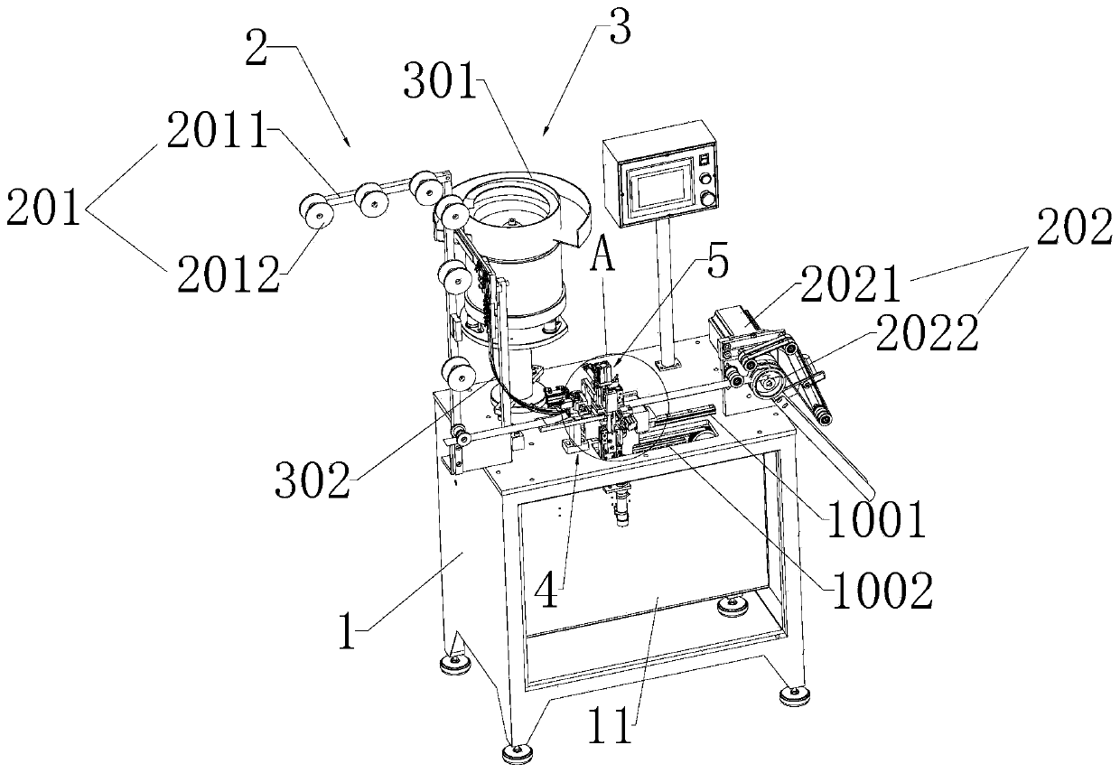
[0050] refer to figure 1 , this embodiment discloses a zipper threading slider machine, including a frame 1, on which a chain belt feeding assembly 2, a slider feeding assembly 3, a chain belt gap detection assembly 4 and a slider threading assembly 5 are arranged, The chain feeder assembly 2 feeds the fastener stringer 12 in the horizontal direction.

[0051] refer to figure 1 The chain feeding belt assembly 2 includes a front guide pulley set 201 and a rear dragging belt assembly 202, the front guide pulley set includes a chain guide frame 2011 fixedly arranged on the frame 1 and a plurality of chain guide wheels rotatably arranged on the chain guide frame 2011 2012, the...


PUM


Abstract

The invention discloses a zipper head passing machine for zippers. The zipper head passing machine for zippers has the scheme that the zipper head passing machine comprises a machine frame, wherein azipper belt conveying assembly, a zipper head conveying assembly, a zipper belt notch detection assembly and a zipper head passing assembly are arranged on the machine frame; the zipper head conveyingassembly comprises a zipper head vibration blanking disc and a zipper head guide slide rail; the tail end of the zipper head guide slide rail is provided with a single zipper head pushing-out assembly; the zipper head passing assembly comprises a horizontal belt guide plate, and also comprises a belt clamping assembly, a zipper belt separating assembly and a zipper head installing assembly; the single zipper head pushing-out assembly is used for conveying the zipper heads to the zipper head installing assembly; the zipper belt conveying assembly drags the zipper belts to be conveyed in the horizontal direction; the horizontal belt guide plate is horizontally and glidingly arranged on the machine frame; the zipper head passing assembly also comprises a horizontal driving assembly; throughthe zipper head passing on the zipper belt in the horizontal direction, the energy consumed in the zipper head passing process is reduced; the efficiency is favorably improved; the influence by gravitational acceleration is reduced; the vibration is reduced; and the use stability of the machine is improved.

Description

technical field [0001] The invention relates to the field of zipper machinery, in particular to a zipper threading slider machine. Background technique [0002] In the zipper production process, in some processes, it is necessary to put zipper pullers on the combined chain belts. In the prior art, automatic slider threading equipment is used to complete this process. [0003] Among them, the Chinese invention patent application with the publication number CN 107495549 A discloses a zipper reverse threading machine for the slider to pass through the chain belt, including a zipper belt action system, which includes a zipper belt feeding device and a hook belt positioning device. and pressing belt fixing device, respectively used for feeding, positioning and fixing the zipper belt; [0004] A slider action system, which includes a slider conveying device and a slider clamping device, which are respectively used to transport and clamp the slider; [0005] A control system, whi...

Claims


Application Information

Patent Timeline
Patent Type & Authority Applications(China)
IPC IPC(8): A44B19/62
CPCA44B19/62
Inventor 段军黄君
Owner 广州市振宇拉链机械有限公司
Why Eureka
Try Eureka